| VANES |
|
1. CATEGORY
1.0 – River Training
2. DESIGN STATUS
Level I
3. ALSO KNOWN AS
Rock vanes, Upstream angled spurs.
4. DESCRIPTION
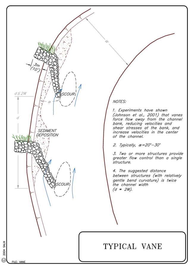
Vanes are redirective, discontinuous, transverse structures angled into the flow in order to reduce local bank erosion by redirecting flow from the near bank to the center of the channel. The instream tips of the structures are typically low enough to be overtopped by all flows and crests slope upward to reach bankfull stage elevation at the bank.
5. PURPOSE
Structures angled upstream redirect overtopping flows away from the protected bank (Biedenharn et al., 1997). Vanes are installed to provide toe protection and rectify lateral instability by redirecting flow away from eroding banks, while providing greater environmental benefits than stone blanket or revetment (Shields et al., 1995). Vanes can increase scour at the tips, backwater area, edge or shoreline length, and the diversity of depth, velocity and substrate (D. Derrick, personal communication, 2002).
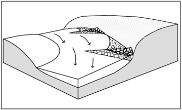
When properly positioned, a vane deflects flow away from the bank and induces deposition upstream and downstream of the structure. This redirection of flow reduces velocity and shear stress along the bank while creating a secondary circulation cell that transfers the energy toward the middle of the channel (Fischenich, 2001). Rock vanes, protruding 1/3 bankfull width into the channel and oriented at an upstream angle between 20° and 30°, move the thalweg an average of 20% bankfull width away from the eroding bank (Johnson et al., 2001).
Therefore, vanes, whether made of rock and/or logs, redirect water away from streambanks into the center of the channel. This serves to decrease shear stress on banks, as well as creating aquatic habitat in the scour pools formed by the redirected flow. By increasing shear stress in the center of the channel, the vanes create a stable width/depth ratio, maintain channel capacity and maintain sediment transport capacity and competence (Rosgen, 2001). J-hook vanes can also be paired and positioned in a channel reach to initiate meander development or migration (Genesee/Finger Lakes RPC, 2001).
6. PLANNING
Useful for Erosion Processes:
Toe erosion with upper bank failure Scour of middle and upper banks by currents
Local scour Erosion of local lenses or layers of noncohesive sediment
Erosion by overbank runoff General bed degradation
Headcutting
Piping
Erosion by navigation waves
Erosion by wind waves
Erosion by ice and debris gouging General bank instability or susceptibility to mass slope failure
Spatial Application:
Instream Toe Midbank Top of Bank
Hydrologic / Geomorphic Setting
Resistive Redirective Continuous Discontinuous Outer Bend Inner Bend Incision Lateral Migration Aggradation Conditions Where Practice Applies:
Vanes are installed on the outside of stream bends where high velocity and shear stress is causing accelerated bank erosion. Vanes can often be used at sites where riprap revetments are traditionally applied but greater environmental benefits are desired. However, vanes and other redirective, discontinuous practices should be applied with caution to project sites where infrastructure is immediately adjacent to the protected bank. Vanes can be combined with longitudinal stone toe or toe or vegetated riprap if continuous resistive protection is also necessary (see Technique: Longitudinal Stone Toe with Spurs and Vegetated Riprap). Vanes have been successfully installed in rivers and streams with bankfull widths ranging from 9 m to150 m (30 ft to 492 ft), with gradients between 0.05 to 0.0003, and in a variety of bed materials (Rosgen, 2001); it is suggested that they only be used in streams with a width/depth ratio of 12 or greater (Maryland, 2000). The ability of vanes to redirect flows and shift local scour and stream power to the center of the channel makes the technique particularly effective where bridge infrastructure is threatened by scour or flanking. Vanes can be used where it is necessary to preserve as much of the existing bank vegetation as possible, and where aquatic habitat and substrate complexity is an important consideration. Unlike riprap revetment, which requires reshaping of the bank for installation, vanes require bank disturbance only where keys are placed. This provides opportunities for using vanes in combination with soil bioengineering techniques.Complexity:
Moderate.Design Guidelines / Typical Drawings:
Regardless of project goals, the key design/construction elements of vanes are length, angle, crest elevation, slope, rock size, the placement of appropriate footer rocks, and vane spacing if using the structures in series.Hydraulic Considerations: The primary hydraulic design consideration for vanes is the water surface elevation of bankfull stage (see Special Topic: Bankfull Discharge). Cross vanes are independent of design high-water and freeboard and vegetation establishment is the most common bank protection from bankfull stage to top of bank.
Length: The vane should extend 1/4 to1/3 the bankfull width of the channel (Rosgen, 2001; Maryland, 2000; Brown 2000). However, this maximum applies to small streams; the larger the channel, the shorter the vane should be relative to the channel width. Untested equations for determining the appropriate length of J-hook vanes based on meander radius of curvature, channel width and vane departure angle are presented in Table 1.
Table 1. Equations for predicting ratio of vane length/bankfull width (VL) as a function of ratio of radius of curvature/width (Rc/W) and departure angle, where W = bankfull width. (SI units)
(Rosgen, 2001)
Rc/W
Departure Angle (degrees)
Equation
3
20
VL = 0.0057 W +0.9462
3
30
VL = 0.0089 W + 0.5933
5
20
VL = 0.0057 W + 1.0462
5
30
VL = 0.0057 W + 0.8462
Angle: Optimum results are obtained when the vane is oriented upstream at an angle with the protected bank between 20° and 30° (Johnson, et al., 2001; Rosgen, 2001). A 20° angle requires a longer vane, but protects a greater length of bank. When orienting vanes for the specific goal of protecting bridge infrastructure, i.e., directing flow through and reducing scour at bridge abutments, a 30° angle is generally more effective at reducing scour at the abutment and moving maximum scour depth toward the center of the channel than the 20° angle (Rosgen, 2001).
Height: The crest elevation of the bank end of the vane should be equal to the bankfull or AHW stage elevation (see Special Topic: Bankfull Discharge). The key into the bank is also designed to bankfull elevation. The vanes must be keyed into the bank at least 3 m (10 ft). If the bank is higher than bankfull, Rosgen suggests building a bench at bankfull elevation to key in the vane. David Derrick (personal communication, 2002) and Biedenharn, et al., (1997) recommend overfilling the keyway to counteract settling and subsequent overland flow erosion of the key prior to backfilling. Additional stability and erosion control can be gained by planting the keyway excavations with Willow Poles or Live Siltation. (See Typical Vane Key Detail, Willow Posts and Poles, Live Siltation, and the Special Topic: The Key to Stability is the Key)
Crest Slope: Vanes are designed to be overtopped at the tip by all but the lowest flows and should pitch from the bank to the tip of the vane with a 3 to 7% slope. Steeper vanes act more like spurs or barbs and have different effects on scour and velocity (Maryland, 2000; Johnson et al., 2001; and Rosgen, 2001).
Rock Gradation and Shape: When possible, vanes should be constructed with graded (self-launching) stone. Self-launching stone will automatically stabilize the toe of the structure in any scour holes that form. Where additional scour is anticipated, more stone may be added to widen the weir crest. In this way, stone may be sacrificed without modifying the crest elevation. The Corps of Engineers has stone gradations for Class A, Class B, and Class C rock (see Special Topic: Self-Launching Stone). Weirs and vanes placed on sand beds devoid of gravel may subside as sand is washed from beneath the stone (Shields et al., 1995); this problem may be addressed by placing filter fabric or a filter layer of finer stone underneath the stone spur.
In sand-bed and gravel-bed streams in Kansas, vanes have been built without the use of underlying filter fabric or stone footers. In these situations additional rock, intended to self-launch, is incorporated into the design. The additional rock is provided by making the vane crests wider and lower with a much wider ‘footprint’ (2 to 4 m). The wider crests reduce the chance that the crest elevation will be affected if rock is ‘launched’. Vanes designed with low and wide crests and constructed with very poorly sorted rock, seem to reduce the potential for scour in sand-bed streams (Phil Balch, personal communication, 2002). In very sandy-bottomed streams, it is advantageous to build vanes using "shot rock" or well-graded stone that includes fines, as they prevent ‘through-flow’ of sand, and subsequent scour.
Rock Size: The size of the rock will depend upon the stream size and shear stress. See comments below under "Hydraulic Loading" on rock sizing. Some state DOTs (or state resource agencies) have published guidelines for specifying rock size, density and durability.
When to use footers: The footer rocks should be heavier, longer, and flatter than the average vane rocks. As a rule of thumb, the weight of the heaviest footer rock is comparable to the heaviest rock used for riprap for the design flow (Maryland, 2000; Harman & Smith, 2000). In sandy streams an extra layer of footer rocks may be necessary to compensate for the additional scour. Even in small sand bed streams, 2 m (6.6 ft) of scour next to a structure like this is not uncommon (D. Shields, personal communication, 2004). Empirical formulas are available for scour depth (Kuhnle et al. 1999 and 2002).
Spacing: The distance from the convergence point of impinging flows along the eroding bank (or upstream corner of a bridge abutment) to the upstream tip of the vane should be twice the channel width (Johnson et al., 2001; Rosgen, 2001). When using vanes in series, the spacing between the upstream tips of the vanes should also be twice the channel width (Maryland, 2000).
Rosgen (2001) suggests the equations in Table 2 for determining appropriate spacing based on meander radius of curvature, channel width and vane departure angle.
Table 2. Equations for predicting ratio of vane spacing/width (Vs) as a function of ratio of radius of curvature/width (Rc/W) and departure angle, where W = bankfull width (SI units) (Rosgen, 2001).
Rc/W
Departure angle (degrees)
Equation
3
20
Vs = - 0.006 W + 2.4781
3
30
Vs = - 0.0114 W + 1.9077
5
20
Vs = - 0.0057 W + 2.5538
5
30
Vs = - 0.0089 W + 2.2067
When using vanes in a series along an outer bend, David Derrick (personal communication, 2000) recommends that the upstream vane be located at the point where impinging flows are first causing erosion. The second vane is located such that the point on the bank that will impacted by the redirected flows are protected by the vane. This method of spacing requires that the design be based the on the flow angles, flow depth and flow direction from the anticipated design storm stage.
As a general rule, small to moderate rivers, less than 20 m (66 ft) wide and where the vane projects approximately 1/3 the width, require spacing that is approximately twice the channel width.
7. ENVIRONMENTAL CONSIDERATIONS / BENEFITS
A large body of evidence indicates that redirective, intermittent structures such as Vanes, Spurs Dikes, and Bendway Weirs provide aquatic habitats superior to resistive, continuous structures like Riprap and Longitudinal Stone Toe (Shields et al., 1995; Brown, 2000; Rosgen, 2001). Controlled scour at the vane tip, the creation of pool/riffle bed complexity, and increased deposition of the upstream end are the major environmental benefits of vanes. The resultant backwater and depositional areas tend to naturally revegetate. Vanes provide fish rearing and benthic habitat, creates or maintains pool and riffle habitat, provides cover and areas for adult fish, and velocity refugia.
Using a redirective measure instead of a continuous, resistive bank armoring technique has several advantages. Vane installation can often be accomplished from the top of the bank, and does not require bank regrading, which minimizes the impacts to existing vegetation and reduces the amount of site disturbance needed for installation. The redirection of impinging flows away from the bank and the sedimentation on the upstream side of the vane creates areas where vegetation can effectively re-establish. Thus, areas of active bank erosion become depositional, vegetate, and subsequently, become permanently stable.
8. HYDRAULIC LOADING
Field results and bench studies have shown vanes to be effective over a range of flow conditions (Johnson et al., 2001; Brown, 2000).
Permissible shear and velocity for rock vanes is related to the size of rock used in construction. Other factors, such as the angularity of the stone, the thickness of the layers of stone, and the angle at which the faces of the stone structure are constructed also come into play.
Detailed guidance for sizing stone for bed and bank stabilization structures is beyond the scope of this guideline, and many approaches are available (see Special Topic: Designing Stone Structures). However, the Maynord (1995) equation gives a D50 stone size for an angular stone riprap revetment of 0.875 m (2.9 ft) if the near-bank vertically-averaged velocity is 3.5 m/s (11.5 ft/s), and flow depth = 1 m (3.3 ft), and stone is placed on a bank slope of 1V:1.5H. Use of riprap larger than this is unusual.
9. COMBINATION OPPORTUNITIES
Since rock vanes can successfully reduce near-bank velocities and shear stress, vegetation establishment is greatly improved. Vanes are often combined with other biotechnical soil stabilization measures for bank areas between the vanes. Vegetated ground cover techniques such as Turf Reinforcement Mats, Erosion Control Blankets, Live Stakes, Live Brush Mattress, and Vegetation Alone are appropriate candidates for combination. Rock vanes are sometimes used in conjunction with continuous and resistive armoring measures, such as Cobble or Gravel Armor, Vegetated Riprap or Longitudinal Stone Toe, when additional protection between the vanes is required. Live Brushlayering, Willow Poles, and Live Siltation are extremely effective when implemented at the bank during excavation of the keyways. Posts and Poles can be used create overhanging cover for pools up- or downstream from cross vanes (Shields et al., 1995).
10. ADVANTAGES
Vanes can be used to reduce streambank erosion, rectify lateral instability, and modify flow direction and local scour, while simultaneously gaining environmental benefits. The technique is appropriate under a range of flow conditions and bed materials and can be used in series to redirect flows around bends. Vane installation does not require extensive bank reshaping, and most heavy equipment work can be done from the top of the bank, further reducing site disturbance. Vanes require less rock and heavy equipment than riprap for a similar length of protected bank. When used to protect bridge infrastructure, vanes placed upstream of abutments force the thalweg toward the center of the channel. Johnson et al. (2001) showed that the thalweg of a movable-bed physical model channel was moved away from the bank an average of 20% of the bankfull width by a well-placed vane.
11. LIMITATIONS
Unintended impacts can result from improper design and construction. If the vane is not properly keyed into the bank, it is likely to fail, creating new localized erosion problems (Rosgen, 2001). Improper vane angle and crest elevation can redirect flow in unintended directions, triggering downstream erosion (Johnson et al., 2001).
12. MATERIALS AND EQUIPMENT
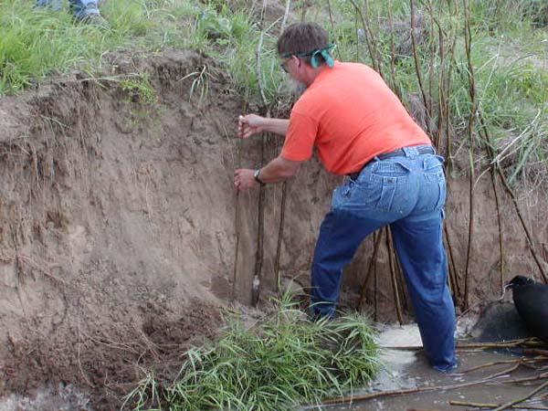
Vanes are generally constructed with graded rock; however, successful vanes have also been constructed from single logs and log cribs with stone fill (Brown, 2000, Rosgen, 2001). An excavator or backhoe is usually needed to construct the keyways and place the vane rocks. Experimental vanes were recently placed in the Ninnescah River in Kansas made from sand-filled, geotextile-wrapped "sausages." These structures were termed "geoberm vanes." The geotextile cylinders were filled using a continuous berm machine.
Appropriate vegetative material must be obtained if Willow Posts and Poles, Live Brushlayering, Live Siltation, Live Brush Mattresses or other biotechnical measures are to be incorporated into the Vanes (e.g., in the key trenches).
 |
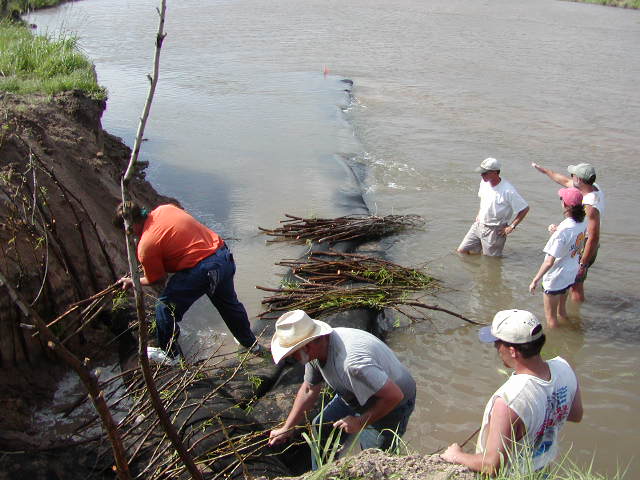 |
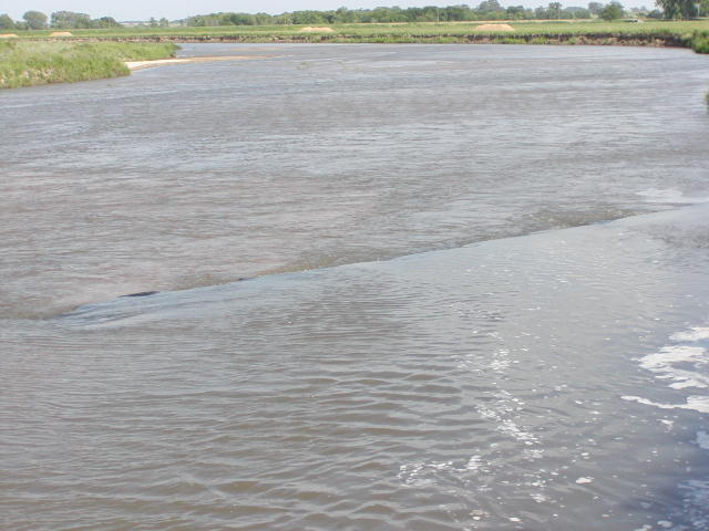
Figure 1.
Experimental
sand-filled geotextile vane, Ninnescah
River, Kansas, 2002. |
|
13. CONSTRUCTION / INSTALLATION
Construction will require excavation of key into the bank at minimum of 3 m (10 ft) to a height of bankfull elevation. If the bank is higher than bankfull, Rosgen suggests building a bench at bankfull elevation to key in the vane. The keyways should be constructed by digging a trench, placing rock and installing vegetation (as described in Willow Posts and Poles), and backfilling. If vegetative techniques are used, such as Willow Post and Poles or Live Siltation, the chances of successful establishment can be increased by "watering in" the cuttings.
Self launching rock can be placed on the existing substrate, however, if footer rocks are necessary, then excavation of the trench for the footer rocks will be required. The depth of the trench varies depending on bed material. For a gravel or cobble bed stream, a depth of twice the diameter of the average vane rock is recommended for the footer trench (Rosgen, 2001; Maryland, 2000). The footer rocks should be placed with a gap between the stones equal to 1/3 their diameter which allows them to interlock as the vane adjusts and equilibrates (Rosgen, 2001). In sandy bed material, or where excessive scour is predicted, the trench depth should be four times the diameter of the average vane rock and the gaps between the rocks should be eliminated. It may be feasible to place a filter fabric geotextile under the footer stones on sand-bed streams. See Rock Gradations above.
 |
 |
 |
|
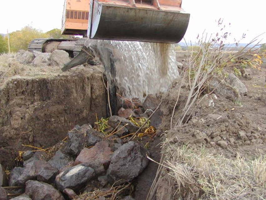
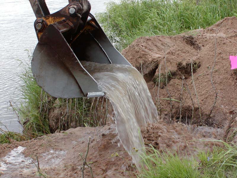
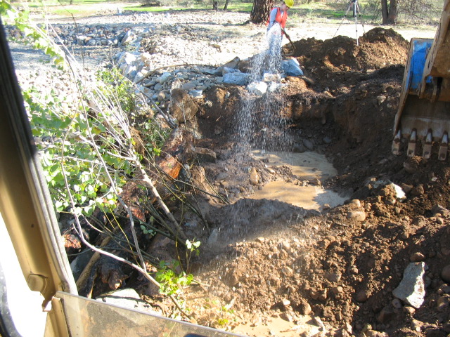
"Watering in"
of cuttings during installation. |
|
14. COST
A reasonable relative cost to riprap is 0.5. It is assumed that under appropriate conditions, vanes can provide protection equivalent to rock riprap at approximately 1/2 the cost which is estimated at $148.00 per linear m ($46.25 per linear ft) of bank. Rosgen (2001) notes that a vane protects a minimum bank length of twice the vane length and this observation has been verified and demonstrated in several instances.
Two geotextile bag Vanes built on the Ninnescah River, Kansas cost a total of $1170.
 |
|
15. MAINTENANCE / MONITORING
The vane should be inspected regularly. Maintenance staff should determine:
Is the vane intact?
Are flows being redirected where expected?
Is there any unintended scour?
Is there deposition on the upstream side of the vane?
16. COMMON REASONS / CIRCUMSTANCES FOR FAILURE
Unintended impacts can result from improper design and construction. If the vane is not properly keyed into the bank, it is likely to fail, creating new localized erosion problems (Rosgen, 2001). Improper vane angle and height can redirect flow to unintended places, creating further bank erosion downstream of the structures (Johnson et al., 2001).
17. CASE STUDIES AND EXAMPLES
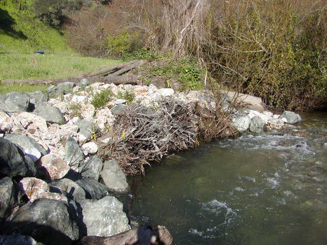
Flood flows from large storms in the winter of 1996 to 1997 resulted in erosion of a streambank on San Vacinte Creek, a coho salmon stream in California, that threatened three residential structures located on the high right-descending bank, and undermined an existing section of rock-filled gabion baskets protecting a commercial establishment located at the lower project reach. In 1998 to 99, vegetated riprap protection was installed along the 183 m (600 ft) project reach. In 2001, a Rock Vane and two Rootwad Revetment structures were installed. The rock vane was designed to redirect flows at a better angle into the riprap revetment. The rootwad structures were intended for bank protection, scour pool formation, cover and habitat complexity. The rootwads and bank were also planted with Live Brushlayering and Willow Poles for long-term stability.
 |
 |
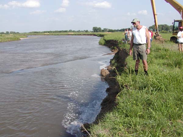
| The previously
installed riprap, 1-2 ton boulders, was not sufficient to arrest
erosion because of extreme "angle of
attack". |
|
 |
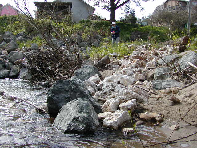 |
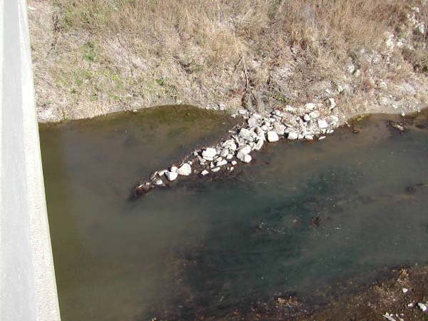
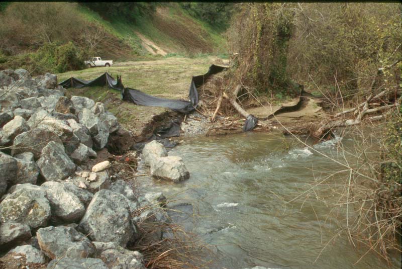
| Rock vane, after severe winter storms had gone out of
bank. Note sediment deposit over tip of vane at right. San Vacinte Creek,
CA |
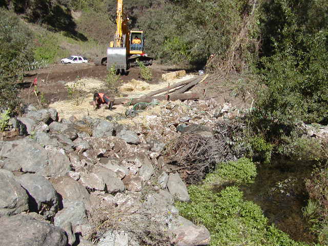
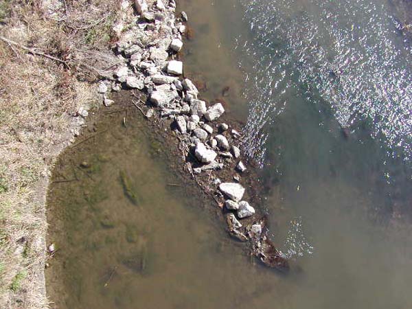
Rock vane,
looking downstream shows evidence of redirecting flows and encouraging
deposition. San Vacinte Creek, CA |
 |
|
|
|
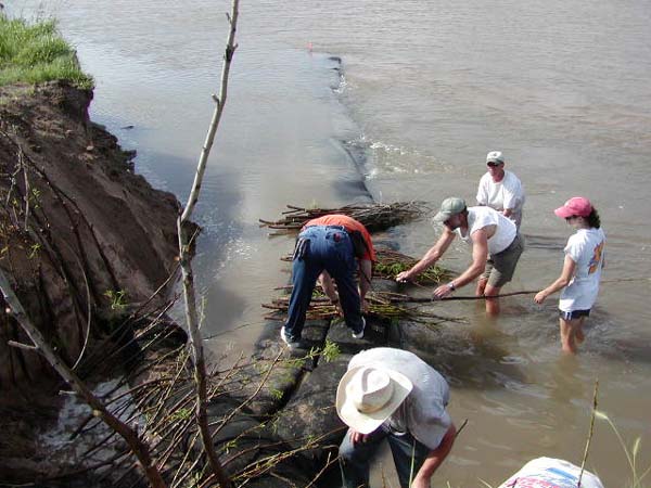 |
"Keying in" the Continuous Berm "Sausage" Vane using brushlayering. |
Please visit the Photo Gallery for more pictures.
18. RESEARCH OPPORTUNITIES
Vanes constructed from relatively small stone have withstood much higher estimated velocities than adjacent riprap constructed with much larger diameter stone. It is possible that rock vanes, because of their acute angle to the flow, might withstand higher velocities and shear that standard shear equations would predict. More research needs to be done in this area.
Definitive guidance based on scientific tests for determining vane design, including angle, elevation, and spacing is needed. An analysis of scour potential for different substrates with regards to redirective techniques is needed.
19. REFERENCES Biedenharn, D. S., Elliott, C. M., & Watson, C. C. (1997).
The WES Stream Investigation and Streambank Stabilization Handbook.
US Army Engineer Waterways Experiment Station, Vicksburg, Mississippi. (pdf)
Brown, K. (2000). Urban Stream Practices: An Initial Assessment.
Center for Watershed Protection, Ellicott City, MD. (pdf)
Fischenich, J. C. (2001). Impacts of stabilization measures. EMRRP Technical
Notes Collection (ERDC TN-EMRRP-SR-32), U.S. Army Engineer Research and
Development Center, Vicksburg, MS. (pdf)
Fischenich, J. C., & Allen, H. (2000). Chapter 5 Soil Bioengineering in Stream Management (ERDC/EL SR-W-00-1) U.S. Army Engineer Research and Development Center, Vicksburg, MS.(pdf)
Genesee/Finger Lakes Regional Planning Council (2001). Cayuga Lake Watershed Restoration and Protection Plan. Sec: Cayuga Lake Watershed Stream Restoration, Rock Vanes www.cayugawatershed.org
Harman, W., & Smith, R. (2000). Using Root Wads and Rock Vanes for
Streambank Stabilization. River Course, Fact Sheet Number 4, NC
A&T State University, North Carolina Cooperative Extension Service,
Raleigh, NC. (pdf)
Johnson, P. A., Hey, R. D., Tessier, M. & Rosgen, D. L. (2001). Use
of Vanes for Control of Scour at Vertical Wall Abutments. Journal of
Hydraulic Engineering, 127:3 772-778.
Kuhnle, R. A., Alonso, C. V., & Shields, F. D., Jr. (1999). Volume of scour holes associated with 90-degree spur dikes. Journal of Hydraulic Engineering 125(9):972-978.
Kuhnle, R. A., Alonso, C. V., & Shields, F. D., Jr. (2002). Local scour associated with angled spur dikes. Journal of Hydraulic Engineering 128(12):1087-1093 (pdf)
Maryland Department of the Environment, Water Management Administration (Follweiler, J eds.) (2000). Maryland’s Waterway Construction Guidelines, Section 3 Channel Stabilization and Rehabilitation Techniques, Baltimore, MD. (pdf)
Maynord, S. T. (1995). Corps riprap design guidance for channel protection.
In C. R. Thorne, S. R. Abt, F. B. J. Barends, S. T. Maynord, and K. W. Pilarczyk.
(eds.). River, coastal and shoreline protection: erosion control using
riprap and armourstone. John Wiley & Sons, Ltd., Chichester, U.
K., 41-42.
McCullah, J.A (2004). Bio Draw 3.0. Salix Applied Earthcare,
Redding, CA
Rosgen, D. L. (2001) The Cross-Vane, W-Weir and J-Hook Vane Structures.
Their Description, Design, and Application for Stream Stabilization and
River Restoration. Wildland Hydrology, Inc. Pagosa Springs, CO. (pdf)
Shields, F. D., Jr., Cooper, C. M., & Testa, S. (1995).
Towards greener riprap: environmental considerations from micro- to macroscale.
In C. R. Thorne, S. R. Abt, F. B. J. Barends, S. T. Maynord, & K W.
Pilarczyk. (eds.). River, coastal and shoreline protection: erosion
control using riprap and armourstone. John Wiley & Sons,
Ltd., Chichester, U. K., 557-574. (pdf)