| LIVE BRUSHLAYERING |
|
1. CATEGORY
1.0 – River Training
2. DESIGN STATUS
Level I
3. ALSO KNOWN AS
Brushlayering
4. DESCRIPTION
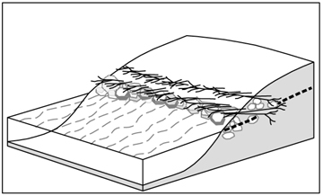
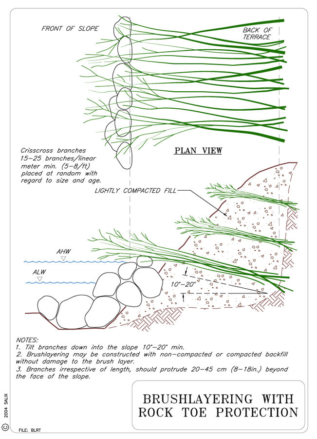
Live brushlayers are rows of live woody cuttings that are layered, alternating with successive lifts of soil fill, to construct a reinforced slope or embankment. The branches are placed horizontally and perpendicular to the run of slope such that the tips protrude just beyond the face of the slope. Vertical spacing depends on soil conditions. A widely-used variation is to wrap or reinforce the soil face with geotextiles or wire (see Technique: Vegetated Mechanically Stabilized Earth).
5. PURPOSE
This technique is used to stabilize slopes, particularly road or stream bank
fill slopes where construction has or will result in unstable soil conditions.
The horizontally-placed branches immediately reinforce slopes because their
mobilized tensile strength resists unbalanced lateral earth forces, and increases
frictional resistance to sliding or other types of displacement. As the roots
grow, the shear strength of the root-permeated soil mass increases, which provides
even greater resistance to failure. The protruding brushy tips retard runoff,
reduce surface erosion and increase the resistance to shallow mass movement.
The branches and leaves provide cover, habitat and improved aesthetics. Brushlayering
provides limited horizontal drainage which can reduce pore pressure and
undermining of
the bank by seepage erosion.
6. PLANNING
Useful for Erosion Processes:
Toe erosion with upper bank failure Scour of middle and upper banks by currents Local scour Erosion of local lenses or layers of noncohesive sediment Erosion by overbank runoff General bed degradation Headcutting Piping Erosion by navigation waves Erosion by wind waves Erosion by ice and debris gouging General bank instability or susceptibility to mass slope failure
Spatial Application:
Instream Toe Midbank Top of Bank
Hydrologic / Geomorphic Setting
Resistive Redirective Continuous Discontinuous Outer Bend Inner Bend Incision Lateral Migration Aggradation Conditions Where Practice Applies:
Brushlayering is suitable for a wide range of climatic, geomorphic, and geographical regions. It has been successfully used in high mountainous terrain, coastal zones, and desert regions. A rule of thumb states that if the desired species of woody shrub that can produce adventitious roots (salix spp., populus spp., cornus spp. for example) are naturally occurring in the general area of the project, then brushlayering is a practicable candidate.
Of all vegetative biotechnical techniques, brushlayering has the greatest capacity for becoming successfully established, even in severe sites. Brushlayering is installed during soil fill operations which result in the branches being inserted deeply into the slopes and thereby increasing the likelihood that the branches will encounter optimum soil and moisture conditions. Brushlayering is particularly appropriate for highway embankments that encroach upon riparian areas or floodways.
Slopes that need additional geotechnical and erosion reinforcement are good candidates for brushlayering. Slopes or streambanks up to 1V:1.5H that are susceptible to surface erosion and/or shallow mass movement can be stabilized by brushlayering. Steeper slopes require the concomitant use of inert reinforcements such as geotextiles (ECBs, TRMs, coir netting), wire (twisted or welded gabion wire) or geogrids (see Technique: Vegetated Mechanically Stabilized Earth). The use of synthetic geotextiles or geogrids provides long-term durability and greater security, especially if woody and herbaceous vegetation is established.
The live branch tips of the brushlayers protrude in horizontal rows ranging from .5 m to 2 m (1.5 ft to 6 ft) apart, vertically.
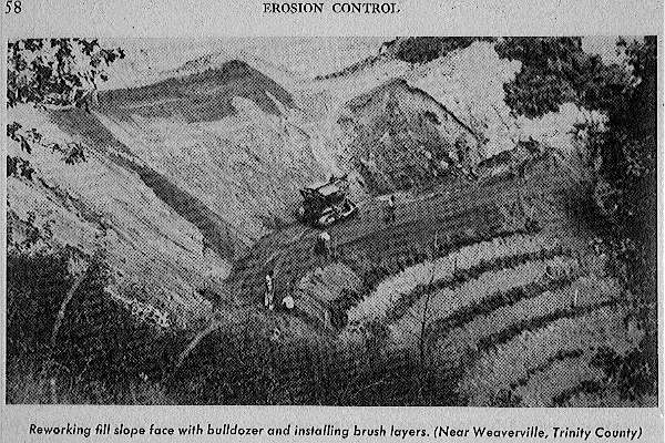
Brushlayering technique used on a highway fill embankment circa 1940. Photo excerpt from Erosion Control Manual, California Dept. of Transportation, 1950
If either steady, long term seepage or temporary bank return flows after flood events are a problem, the brush layers act as a horizontal drainage layer or conduits that relieve internal pore water pressure and favorably modify the groundwater flow regime within the slope to minimize slope stability problems.
Complexity:
Moderate. Brushlayering is more complex than live fascines and live staking, but is still relatively simple to install.
Design Guidelines / Typical Drawings:
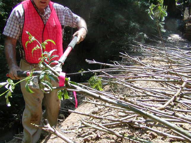
Live branches and brushy cuttings are used to make brushlayers. Up to 30% of the brush may be non-rooting species that provide immediate strength to the soil mass, but will then rot away. Plant material harvesting and installation should be performed during its dormant season (late fall to early spring) or in other seasons if soil moisture is available (See Special Topic: Harvesting and Handling of Woody Cuttings). The ideal plant materials for brushlayers are those that: 1) root easily; 2) are long, straight and flexible; and 3) are in plentiful supply near the job site. Willow (Salix spp.) makes ideal brushlayer material, and some species of Baccharis, Cornus, and Populus also have very good rooting ability. Research indicates that all cuttings should be soaked for a minimum of 24 hours, whether they are stored or harvested and immediately installed (Hoag et al., 1991a; Hoag et al., 1991b; Hoag et al., 1993). Some research recommends soaking the cuttings for as much as 10 to 14 days (Briggs and Munda, 1992; Frenchel et al., 1988; Schaff, Pezeshki & Shields, 2002).
Brushlayer reinforced fills must have adequate internal stability. This means that the tensile inclusions, i.e., the brushlayers, should have a sufficient unit tensile resistance and/or be placed in sufficient numbers to resist breaking in tension. The inclusions must also be sufficiently long and "frictional" enough to resist failure by pullout. The resistance of the brush reinforcement layers to pullout and tensile failure can be analyzed using conventional methods (Bonaparte et al., 1987) developed for earth slopes reinforced with inert tensile inclusions, e.g., geotextiles and geogrids.
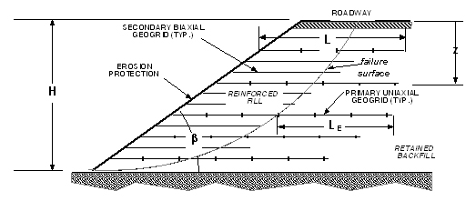
The main considerations in the design of reinforced earthen slopes and embankment fills is the required vertical spacing (d) and total length (L) of the reinforcing layers. The total length (L) is comprised of a length or distance required to reach the expected failure surface in the backfill and an additional length, the effective or embedment length (LE), extending beyond the failure surface required to prevent pullout. The various soil/slope/reinforcement parameters that affect these two design variables are shown schematically in Figure 1.
Both the required vertical spacing and imbedment length vary inversely with the depth of the reinforcing layer, i.e., closer spacing is required at greater depths where shear stresses are highest and shorter imbedment lengths are required at greater depths because of increased normal stresses. A conservative design procedure would be to calculate a fixed vertical spacing based on the maximum placement depth (i.e., height of bank or reinforced fill) and fixed length based on minimum placement depth (i.e., at the ground surface where the failure surface is farthest away from the face of the wall).
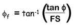
Figure 1. Schematic illustration of soil/slope reinforcement parameters affecting the required spacing and length of geogrid reinforcements.If the front face is battered or sloped back, the unbalanced lateral earth force is reduced considerably, and less demand is placed on the imbedded (internal) reinforcements to maintain equilibrium. Bonaparte et al. (1987) describe a simplified design procedure for geogrid/geotextile reinforced slopes that takes into the account the slope angle. This procedure assumes a bi-linear "sliding wedge" failure mechanism and a cohesionless fill. The chart shown in Figure 2 was developed to calculate the tensile resisting force per unit width of slope required to maintain equilibrium in the slope as a function of slope angle (β) and a factored friction angle (Φf). The factored friction angle is given by
Figure 2. Slope reinforcement design chart for determination of the force coefficient, K, for the design of reinforced slopes constructed with a granular, free draining fill (adapted from Bonaparte et al., 1987)Figure 2 is used to determine a lateral force coefficient (K). As the slope angle (β) decreases, so too does the coefficient (K). Also note that in the case of a typical dry sandy soil (Φ ≈ 30°) at its angle of repose (β = 30°, FS = 1) the lateral earth force coefficient (K) goes to zero! The total required tensile resistance force (T) per unit width of slope to maintain slope stability as some specified factor of safety (FS) is given by the following equation:
Where: K = dimensionless lateral earth force coefficient (given by Figure 2); γ = unit weight of soil fill; and H = height of slope, (FS) = desired factor of safety; Φ = the angle of internal friction of the backfill; and β = slope angle. The total number of reinforcing layers (N) of selected geogrid or geotextile to maintain stability at the specified factor of safety is given by
Where: Tallow = the allowable unit tensile load in the geotextile or brushlayer. These reinforcing layers must be distributed or spaced over the height of the slope. The required vertical spacing (d) is given by the following equation:
where: z = the depth measured from the top of the slope. The smallest required (critical) spacing and "average" spacing occur when z = H and z = 0.5H, respectively. The slope can be split up into zones to determine the required vertical spacing within each zone.
The allowable unit tensile resistance T allow for a brushlayer can be estimated from the specified factor of safety (FSB) against tensile failure of the woody brush stems, tensile strength of the brush stems (σB), their average diameter (dB), and number of stems placed per unit width (nB) according to the following relationship:
For a typical brush layer installation: dB = 0.5 in, nB = 4 stems/ft, FSB = 1.5, and σB = 2000 lbs/in2 (average tensile strength of willow). Therefore,
≈ 1050 lbs/ft
The width or thickness of the fill, measured perpendicularly to the slope face should preferably not exceed 2 m (6 ft), as robust rooting will not take place in oxygen-deficient soils. The optimum compaction for vegetation is generally 85-90%. It is actually quite difficult to achieve greater than 90% compaction on the outer face of the embankments even with optimum moisture. The brush layers can benefit from the reduced compaction while countering soil instabilities such as erosion and slumping. Applying moisture to aide compaction also benefits the branches by maintaining conditions which favor rooting.
7. ENVIRONMENTAL CONSIDERATIONS / BENEFITS
Live brushlayers provide immediate soil stability and habitat. Brushlayers and the pioneer vegetation that develops with them allow the establishment of a stable soil-root complex. Both living and non-living brush layers along streambanks enhance fish habitat, providing a source of shade and nutrients, while slowing velocities along the bank during flooding flows.
8. HYDRAULIC LOADING:
Allowable velocity for brushlayering is 3.7 m/s (12.1 ft/s), and allowable shear stress is 19 to 300 N/m2 (0.4 to 6.25 lb/ft2) depending on how long the brushlayers have had to establish (Fischenich, 2001). Schiechtl & Stern (1996) suggest an allowable shear stress of 140 N/m2 (2.92 lb/ft2).
9. COMBINATION OPPORTUNITIES
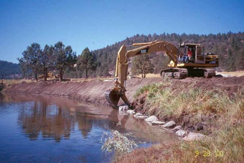
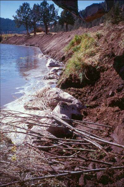
Brushlayering can be used with other toe protection such as, rootwads, coir
rolls, and log toes. Combining live brushlayering with rock toes is an effective
and relatively low cost technique for revegetating and stabilizing streambanks.
10. ADVANTAGES
An advantage of live brushlayers is that they provide a flexible strengthening system to fill slopes. A bank can sag or distort without pulling apart the brushlayers. The brushlayers will "stretch" because they are laid in to the slope on a diagonal, and are also self-repairing to the extent that they re-grow roots in the case of a shear failure. Brushlayers act as horizontal drains and favorably modify the soil water flow regime.
11. LIMITATIONS
Techniques requiring live cuttings are most effective when implemented during the dormancy period of chosen plant species. Brushlayers are vulnerable to failure before rooting occurs, and they are not effective at counteracting failure along very deep-seated failure planes.
12. MATERIALS AND EQUIPMENT
Live willow branches (or cuttings of other adventitiously-rooting species)
at least 1.8 m (6 ft) long, with a minimum diameter of 20 mm (¾ in).
Heavy equipment is usually employed for the construction of embankments.
A bucket loader and/or backhoe or excavator can facilitate the work. Water
should be available for achieving optimum soil moisture.
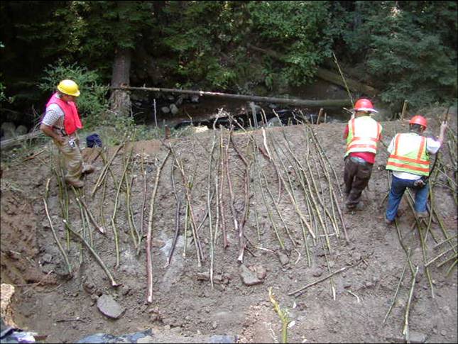
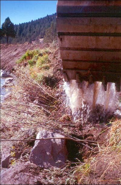
13. CONSTRUCTION / INSTALLATION:
First construct any lower bank or in-stream stabilizing measures such as a rock or log toe structure. Excavate the first horizontal bench, sloping back into the hillslope at about 10%. Install any drainage required along the back of each bench.
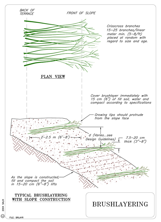
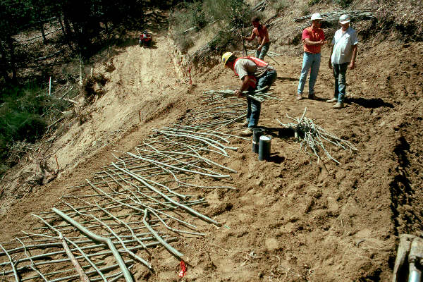
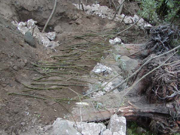
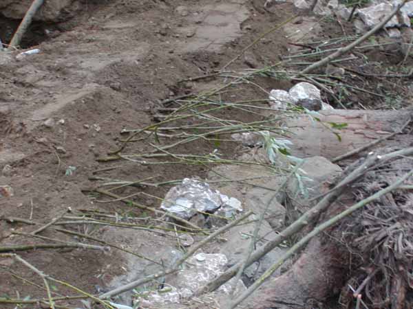
Place branches that are at least 1.8 m (6 ft) long on the bench. Branches should crisscross at random with regard to size and age. Place 20 branches per linear m (5 to 8 branches per linear ft) on the bench, with the butts of the branches along the inside edge of the bench. 20-45 cm (8 to18 in) of the growing tip should protrude beyond the face of the slope. Cover and compact (add water if necessary) the brush layer with 15 cm (6 in) lifts of soil to reach the designed vertical spacing, typically .5 m to 1.2 m (1.5 ft to 4 ft) apart. Slope the top of each fill bench back into the hill. Construct another brushlayer. When placed, the protruding tips of the cuttings are above the butts due to the back slope of the bench. Proceed up the bank as desired. The erosion and failure potential of the slope (i.e., drainage, soil type, rainfall, and length and steepness of the slope) determine spacing between the brushlayers (see Design Guidelines). On long slopes, brushlayer spacing should be closer at the bottom and spacing may increase near the top of the slope.
14. COSTWashington State (2003) reports costs of $32 to $49 per linear m ($10 to 15 per linear ft) of brushlayering, or $2 per branch, including harvest, transportation, storage, and placement; also reported are costs between $121 and $164 per linear m ($37 and $50 per linear ft) including harvesting and installation. Cost will vary based on the density of branch placement and local construction costs.
15. MAINTENANCE / MONITORING
The live cuttings or branches should establish successfully without irrigation
requirements given the proximity to water. Monitoring basically consist of
inspecting the cuttings for adequate vegetative establishment (as evidenced
by root and shoot production from the imbedded stems) and for signs of localized
erosion such as rilling from runoff or sloughing from stream scour. Brushlayer
treated streambanks should also be inspected for localized slope movements
or slumps. These localized slope failures and/or areas of poor vegetative establishment
can often be repaired by re-installing the brushlayers in these zones. Finally,
the site should be examined for possible signs of flanking erosion, which must
be addressed with ancillary protective measures lest the flanking threaten
the integrity and effectiveness of the protective brushlayer fill.
16. COMMON REASONS / CIRCUMSTANCES FOR FAILURE
The most likely causes of failure are the following:
Inadequate reinforcement from the brushlayer inclusions, i.e., too large a vertical spacing or lift thickness for the given soil and site conditions, viz., slope height, slope angle, and soil shear strength properties,
Inadequate tensile resistance in the brushlayers as result of too small an average stem diameter and/or too few stems per unit width,
Failure to properly consider seepage conditions and install adequate drainage measures, e.g., chimney drain, behind brushlayer fill, and conversely
Inadequate moisture applied during installation, and
Inadequate attention to construction procedures and details.
As with all resistive streambank structures, flanking is always a potential problem. If frozen soil is employed in constructing the soil lifts between brushlayers, some settlement may occur when the soil thaws. This settlement may falsely signal a slope failure.
17. CASE STUDIES AND EXAMPLES
Live Brushlayering has been widely used over the last decade or so. The technique is used for many different slope applications, from highway embankments to streambanks, from riparian corridors in the South east states to high elevation highway corridors in the mountainous Northwest. There are numerous examples of brushlayering.
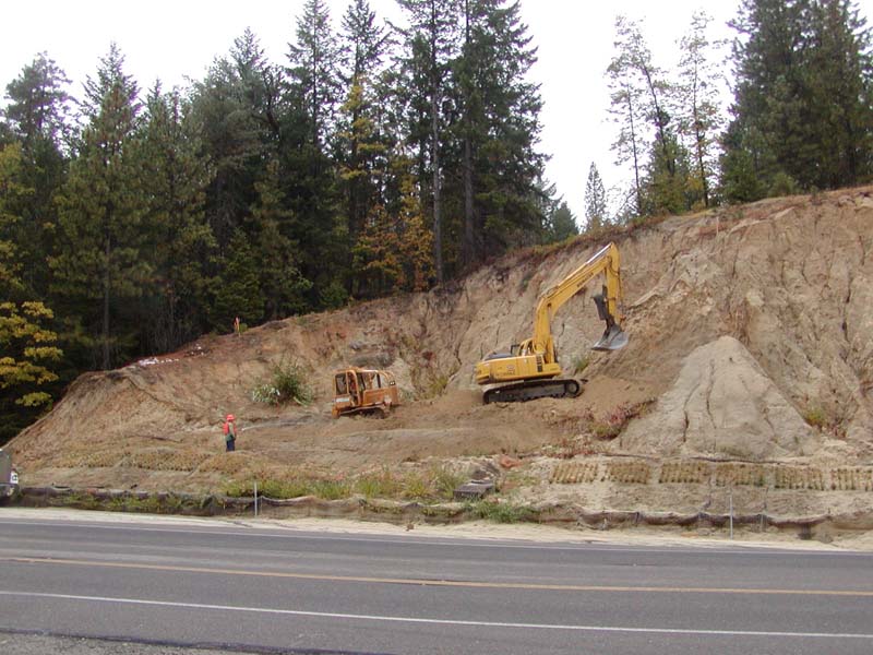
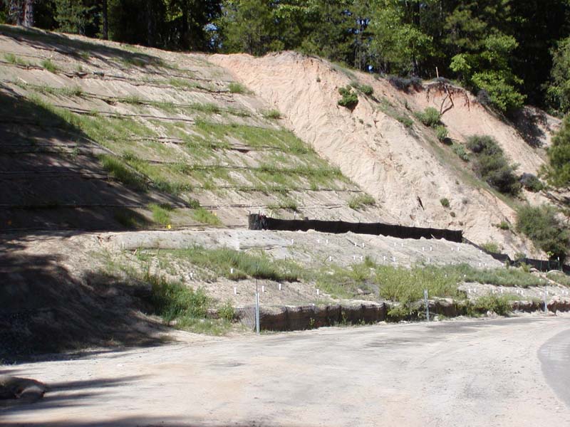
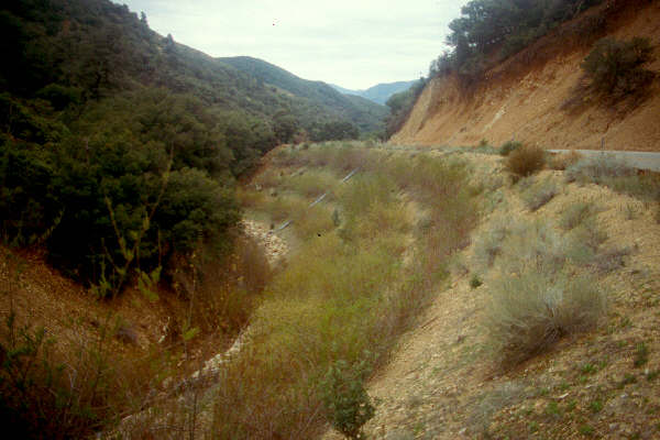
Highway 299W, Buckhorn Mountain, Shasta County/ Trinity County, California.
This mountainous region is characterized by steep terrain underlain by highly erosive decomposed granite. The area receives greater than 152 cm (60 in) of precipitation between October and May while the summer season gets no rainfall and temperatures often exceed 100°F through July and August. Re-establishing vegetation after construction is exceedingly difficult. The geologic and climatic conditions have presented many challenges to the Caltrans highway planners for building a new and safer route over the mountain. Conversely, there have been numerous opportunities to experiment with new construction techniques.
In 1991, Caltrans built two adjacent, 1V:1.5H, fill slope embankment as part of a "curve correction" and research project. One slope was built with conventional construction but utilized a wide array of erosion control products such as hydroseeding, erosion control blankets, etc. The other slope was built with brushlayering. The brushlayering used willow cuttings, 1.5 to 2 m (5 to 6.6 ft) long, and was constructed in August during 100°F weather. The branches were soaked less than 24 hours (see Special Topic: Harvest and Handling of Woody Cuttings for recommended soaking) and the 3 to 4 m (10 to 13 ft) vertical spacing was too great.
Even though the design and construction was not ideal, the slope has performed well. In December following construction, the area received a large snow event (0.6 m (2 ft)) followed by almost 25 cm (10 in) of rain in 72 hours. After this "rain on snow" event the fill slope with standard practices failed severely and eventually had to be reconstructed at a significant cost. The slope with live brushlayering ended up with severe gullies by the end of winter but hand crews were able to make the necessary repairs, again using brushlayers, in one day.
 |
 |
|
|
 |
 |
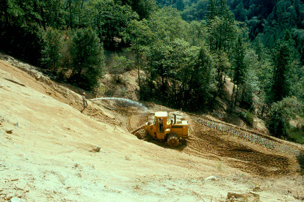
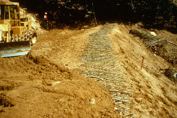
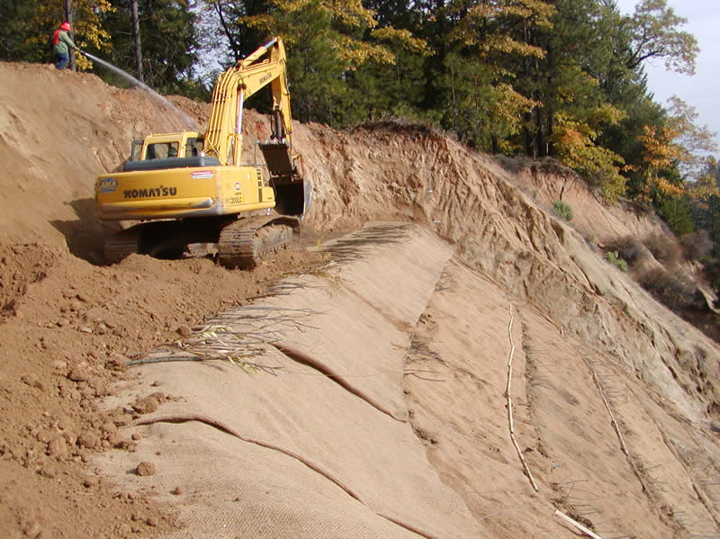
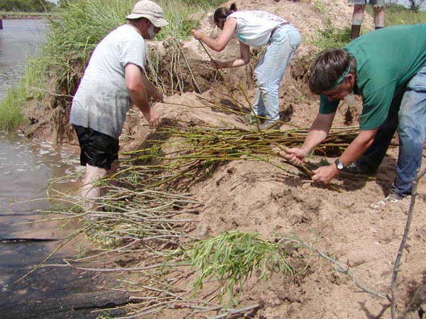
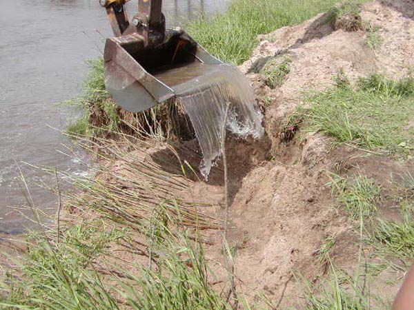
| The branches were
covered with 20 cm (8”)
of soil before compacting. August 1991. Photo by J. McCullah |
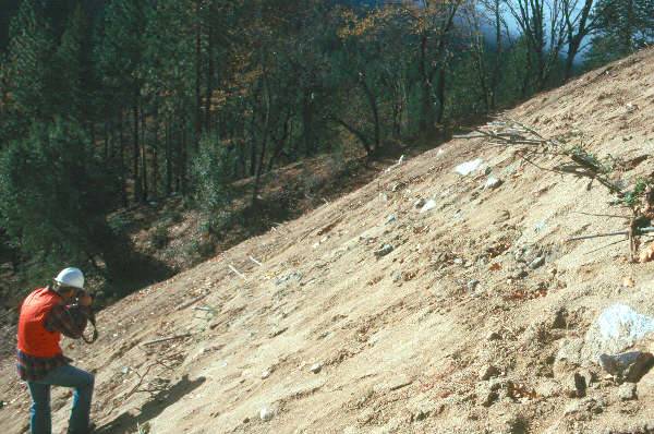
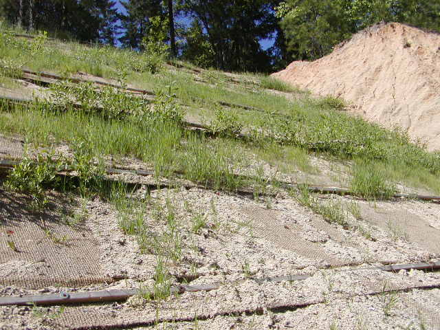
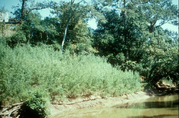
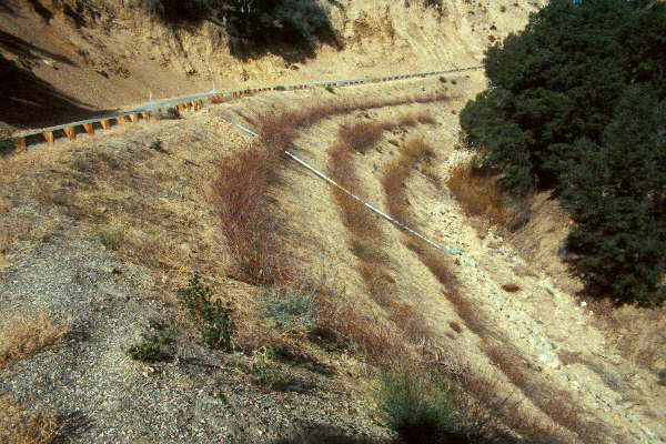
Brushlayer slope after
construction. September 1991. Photo by J. McCullah |
 |
 |
|
|
 |
 |
|
|
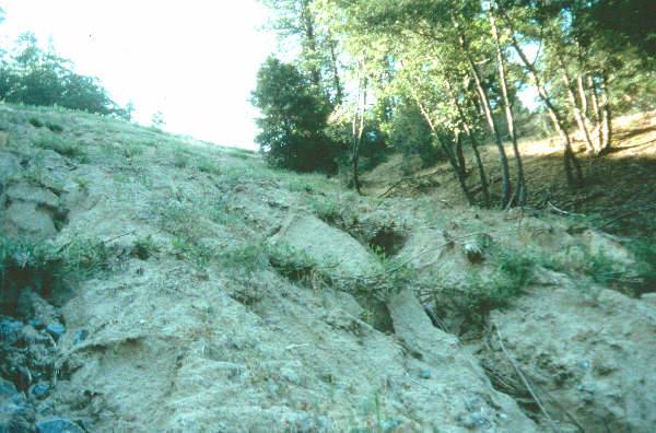
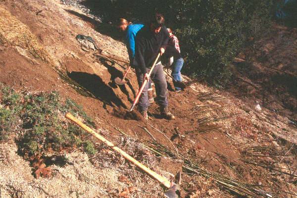
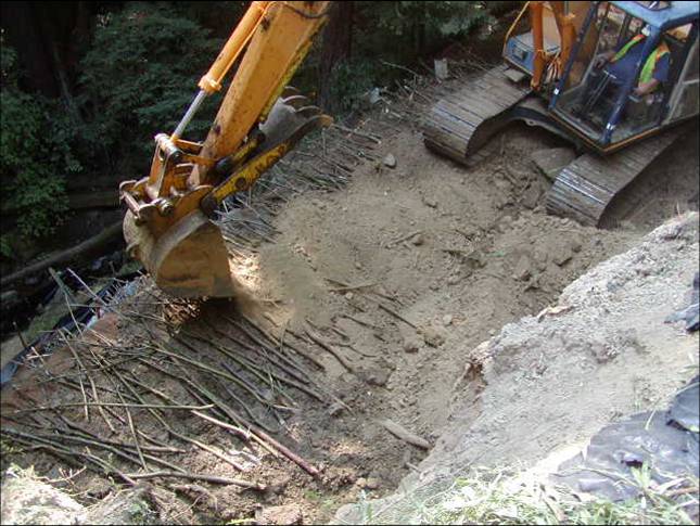
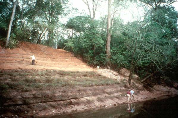
Zayante Creek Road.
This landslide in the redwood forests of Santa Cruz County, was repaired as part of a week-long training for County Road Department crews. Because Zayante Creek, at the toe of the slide, provides valuable Coho salmon habitat, the agencies were looking for alternative, environmentally-sensitive measures that were also cost-effective.
A weighted rock toe was keyed into the bottom of the slope at the edge of the stream. Brushlayering, willow poles and VMSE were utilized as the embankment was rebuilt. The geotextile used for the VMSE was a polypropylene-coir composite with long durability and high tensile strength. Brushlayers were placed in 1 m (3 ft) vertical lifts and inserted into the slope 2 to 3 m (6.6 to 10 ft).
The Road Department engineer reported that this technique was less than the cost to build a comparable rock-filled cribwall. The personnel and equipment costs were alike while the materials were much cheaper. This project was built in August, a period with no precipitation. The County was supposed to arrange for one or two irrigations with a water truck. The irrigation did not occur so the actual willow establishment was less than ideal, however, willow growth is not necessary for slope stabilization.
 |
 |
|
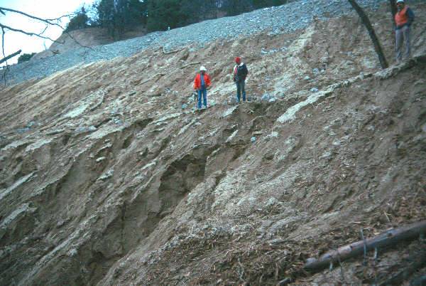
Zayante Creek in background.
Branches covered with soil layer (6” thick) before tractor
compacted. |
 |
 |
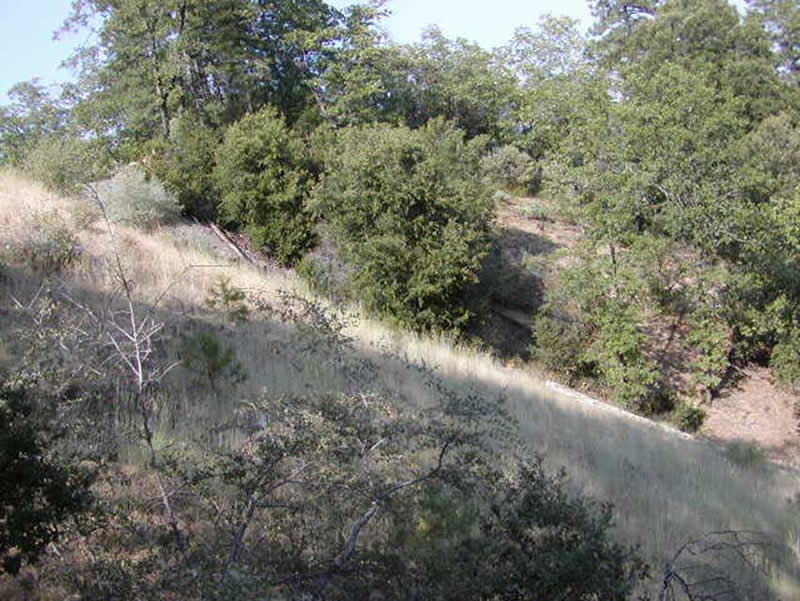
|
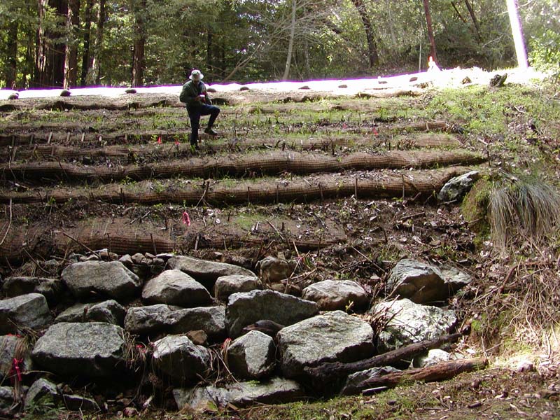
The landslide repair after 9 months evaluated by Dr. Donald Gray.
March 2003 Photo by J. McCullah. |
Miscellaneous Examples
 |
 |
|
|
 |
 |
|
|
 |
||
|
|
|
 |
||
|
||
 |
 |
 |
|
|
|
 |
 |
|
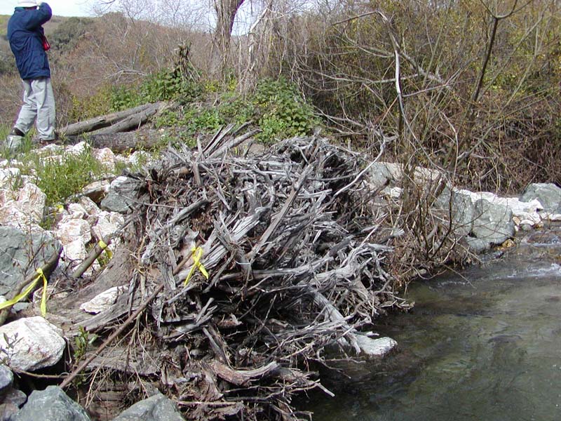
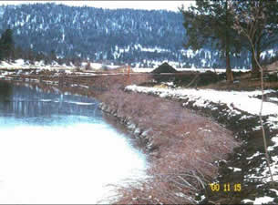
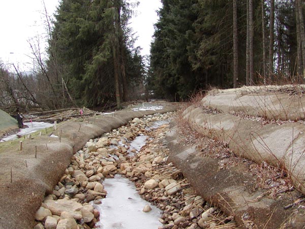
| Brushlayering
with rock toe along Reach D during the first winter. Photo by J.
McCullah. |
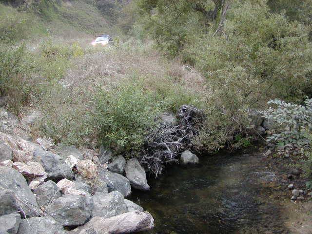
Brushlayering
with rock toe, Reach D, Bushey Ranch, after 2 years.
|
|
 Before |
 After 4 years |
 |
 |
| Live Brushlayering Installation, Ninnescah River, Kansas | |
 |
 |
|
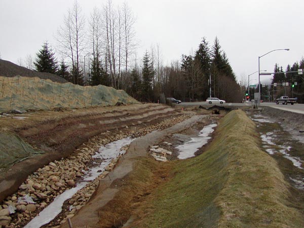
Alaska DOT project showing Brushlayers
improperly installed. Branch tips are pointing down, and live stakes
are not deeply planted.
|
|
Please visit the Photo Gallery for more pictures.
18. RESEARCH OPPORTUNITIES
A need exists to study carefully the performance of brushlayer protected streambanks that are subjected to stream ice.
19. REFERENCES
Bonaparte, R., Holtz, R.D., & Giroud, J.P. (1987). Soil reinforcement design
using geotextiles and geogrids. Geotextile Testing and the Design Engineer,
ASTM STP 952, J.E. Fluet, Jr., ed., American Society for Testing and Materials,
Philadelphia , 1987, pp. 69-116
Briggs, J.A., and Munda, B. (1992). "Collection, Evaluation and Production of Cottonwood Poles for Riparian Area Improvement", final Report to the U.S. F.W.Service, U.S.D.A.-S.C.S., Tucson Plant Materials Center, Tucson, AZ.
Fischenich, J. C. (2001). Stability thresholds for stream restoration materials. EMRRP Technical Notes Collection (ERDC-TN-EMRRP-SR-29), U.S. Army Engineering Research and Development Center , Vicksburg , MS.
Fenchel, G., W. Oaks & Swenson, E.. (1988). Selecting Desirable Woody
Vegetation for Environmental Mitigation and Controlling Wind Erosion and
Undesirable Plants in the Rio Grande and Pecos River Valleys of New Mexico. Five
year interim report (1988-87).: USDA-SCS Los Lunas Plant Materials Center.
Los Lunas, NM.
Hoag, J. C., (1993). How to plant willows and cottonwoods for riparian rehabilitation.
USDA Natural Resources Conservation Service, (Idaho Plant Materials Technical
Note #23), Boise, ID.(pdf)
Hoag, J. C., Young G. L., & Gibbs J. L. (1991a). Advanced Regional Adaptation Trials of Accessions from the Aberdeen Plant Materials Center. Paper presented at the 45th Annual Meeting of the Society for Range Management, Spokane, WA.
Hoag, J. C., Young G. L., & Gibbs J. L. (1991b). Planting Techniques for Vegetating Riparian areas from the Aberdeen Plant Materials Center. Paper presented at the 45th Annual Meeting of the Society for Range Management, Spokane, WA.(pdf)
Schaff, S. D., Pezeshki, S. R. & Shields, F. D. (2002). Effects of Pre-Planting Soaking on Growth and Survival of Black Willow Cuttings. Restoration Ecology. Vol. 10, No. 2, pp. 267-274
Schiechtl, H. M. & Stern, R. (1996). Water Bioengineering Techniques for Watercourse Bank and Shoreline Protection . Blackwell Science, Inc. 224 pp.
Washington Dept of Fish & Wildlife (2003). Integrated Streambank Protection
Guidelines, published in co-operation with Washington Dept. of Transportation
and Washington Dept. of Ecology, June 2003. (Chapter 6 pdf)
(Appendix L pdf)
(Appendix H pdf) http://www.wa.gov/wdfw/hab/ahg/ispgdoc.htm (April
2003)


