| VEGETATED
MECHANICALLY STABILIZED EARTH |
 |
| VEGETATED
MECHANICALLY STABILIZED EARTH |
|
1. CATEGORY
1.0 River Training
2. DESIGN STATUS
Level I
3. ALSO KNOWN AS
Vegetated geogrids, brushlayering with soil wraps, vegetated geofabric wrapped soil.
4. DESCRIPTION
This technique consists of live cut branches (brushlayers) interspersed between lifts of soil wrapped in natural fabric, e.g., coir, or synthetic geotextiles or geogrids. The live brush is placed in a criss-cross or overlapping pattern atop each wrapped soil lift in a manner similar to conventional brushlayering (see Technique: Live Brushlayering). The fabric wrapping provides the primary reinforcement in a manner similar to that of conventional mechanically-stabilized earth (Koerner, 1998; Mitchell & Villet, 1987). The live, cut branches eventually root and leaf out, providing vegetative cover and secondary reinforcement as well. In some cases, the vegetative treatment may consist of using a coarse netting for the soil wraps and establishing an herbaceous or grass cover by simply hydroseeding through the openings in the fabric (Gray & Sotir, 1996).
5. PURPOSE
Vegetated Mechanically Stabilized Earth (VMSE) can be viewed as a union between conventional, mechanically stabilized earth methods that utilize inert, tensile inclusions, and brushlayering, a soil bioengineering technique that utilizes live, cut branches as the tensile soil inclusions. The treatments complement one another. Fabric wraps provide the primary reinforcement and mechanical stabilization, permitting much steeper slopes to be constructed than would be possible with live brushlayers alone. The vegetation shields the fabric against damaging UV radiation and provides visual and habitat benefits.
6. PLANNING
Useful for Erosion Processes:
Toe erosion with upper bank failure Scour of middle and upper banks by currents Local scour Erosion of local lenses or layers of noncohesive sediment Erosion by overbank runoff General bed degradation Headcutting Piping Erosion by navigation waves Erosion by wind waves Erosion by ice and debris gouging General bank instability or susceptibility to mass slope failure
Spatial Application:
Instream Toe Midbank Top of Bank
Hydrologic / Geomorphic Setting
Resistive Redirective Continuous Discontinuous Outer Bend Inner Bend Incision Lateral Migration Aggradation Conditions Where Practice Applies:
VMSE can be used to stabilize slopes as steep as 1V:0.5H. This technique provides an alternative to vertical retaining structures, e.g., timber pile walls, and to techniques that require slope flattening or bank lay back, which results in excessive right-of-way encroachment at the top of bank. The use of synthetic geotextiles or geogrids provides greater long-term durability and security. The fabric or geotextile wrap also provides additional protection to upper portions of streambanks that are subject to periodic scour or tractive stresses. If either steady, long term seepage or temporary bank return flows after flood events are a problem, the brushlayers act as a drainage layer or conduits that relieve internal pore water pressure, and favorably modify the groundwater flow regime within the slope to minimize slope stability problems.
Complexity:
High. VMSE is relatively complex, because it entails designing, melding together, and constructing two similar yet distinct methods, conventional MSE and live brushlayering. Both techniques are widely used and well understood, however; simultaneous use introduces complexity.
Design Guidelines / Typical Drawings:
Many different types of inclusions with various shapes and properties can be used to reinforce and buttress earthen slopes. These inclusions range from imbedded metal strips, geogrids fabricated from polymeric nets, and natural or synthetic geotextiles or fabrics. Earthen slopes, embankments, or structural fills that are stabilized or reinforced with such tensile inclusions are referred to as "mechanically stabilized earth." Shear stresses that develop in the soil matrix are transferred into tensile resistance in the imbedded inclusions via friction along the soil-inclusion interface.
Mechanically stabilized earth retaining structures must satisfy external stability requirements, i.e., have adequate resistance to sliding, overturning, and bearing capacity failure. Internal stability requirements are also important in reinforced earth and mechanically stabilized earth structures. The tensile inclusions or reinforcements in these structures must have a sufficient unit tensile resistance and/or be placed in sufficient numbers to resist breaking in tension. The inclusions must also be sufficiently long and "frictional" enough to resist failure by pullout.
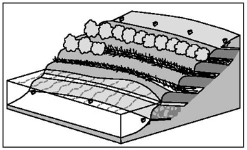
Synthetic geogrids fabricated from high-tensile strength polymeric materials are widely used in reinforced earth embankments and retaining walls. Geogrids tend to have superior pullout resistance compared to geotextile or fabric sheets because of passive resistance mobilized along the transverse elements in a mesh or geogrid. They can be used either in a wrap-around fashion to provide both backfill reinforcement and containment at the front face. This approach permits the insertion of live cuttings or branches between successive lifts of "wrapped soil" as shown schematically in Figure 1.
Live cuttings inserted in the above manner also act as tensile inclusions and help to stabilize a slope, embankment, or structural fill. Live brushlayers behave exactly in this fashion. Gray & Sotir (1992) discuss how brushlayers can be analyzed and their contribution to slope stability determined in a rational, quantitative manner. This contribution could be included as well when inert reinforcements are used in conjunction with live brushlayers such as in VMSE. In this combined approach, however, the contribution to mechanical reinforcement from the live cuttings is simply treated as a bonus, and the design analysis is focused on the fabric or geogrid reinforcements themselves.
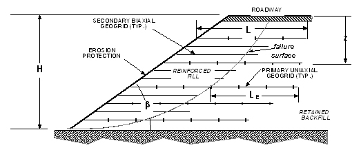
The main considerations in the design of geogrid or geotextile reinforced earthen slopes and embankment fills is the required vertical spacing (d) and total length (L) of the reinforcing layers. The total length (L) is comprised of a length or distance required to reach the expected failure surface in the backfill and an additional length, the effective or imbedment length (LE ), extending beyond the failure surface required to prevent pullout (see Technique: Live Brushlayering for more information). The reader should consult with a geotechnical engineer as necessary. The various soil/slope/reinforcement parameters that affect these two design variables are shown schematically in Figure 2. A general expression (Bonaparte et. al, 1987) for the required spacing (d) and effective (or imbedment) length (LE ) for a vertical, reinforced structure is given by the following equations:
(1)
Figure 1. Conceptual drawing of a vegetated mechanically stabilized earth streambank support application
(adapted from USDA, 1996).
(2)
where: (FS) = desired factor of safety T allow = the allowable unit tensile load in the geogrids K A = the coefficient of active earth pressure z = the depth to the reinforcing layer q = uniform (or equivalent) vertical surcharge γ = the unit weight of the backfill Φ = the angle of internal friction of the backfill; and μ = an interface friction coefficient between soil and reinforcement (approximately unity for geogrids). Both the required vertical spacing and imbedment length vary inversely with the depth of the reinforcing layer; i.e., closer spacings are required at greater depths where shear stresses are highest and shorter imbedment lengths are required at greater depths because of increased normal stresses. A conservative design procedure would be to calculate a fixed vertical spacing based on the maximum placement depth (i.e., height of the bank or reinforced fill) and fixed length based on minimum placement depth (i.e., at the ground surface where the failure surface is farthest away from the face of the wall). Alternatively, the backfill could be subdivided into zones and required spacing and length based on the midpoint depth of each zone. More detailed design guidelines are presented by Mitchell & Villet (1987).
Figure 2. Schematic illustration of soil/slope reinforcement parameters affecting the required spacing and length of geogrid reinforcements
If the front face is battered or sloped back, the unbalanced lateral earth force is reduced considerably, and less demand is placed on the imbedded (internal) reinforcements to maintain equilibrium. Bonaparte et al. (1987) describe a simplified design procedure for geogrid/geotextile reinforced slopes that takes into the account the slope angle. This procedure assumes a bi-linear "sliding wedge" failure mechanism, and a cohesionless fill. The chart shown in Figure 3 was developed to calculate the tensile resisting force per unit width of slope required to maintain equilibrium in the slope as a function of slope angle (β) and a "factored" friction angle (Φf). The factored friction angle is given by:
(Φf) = tan-1 (tan Φ/ FS ) (3)
Figure 3. Slope reinforcement design chart for determination of the force coefficient, K, for the design of geogrid or geotextile reinforced slopes constructed with a granular, free draining fill (adapted from Bonaparte et al., 1987)
Figure 3 is used to determine a lateral force coefficient (K) that is related to the coefficient of active earth pressure (KA) used in Equation 1 for a vertical structure. In the case of a vertical slope (β =90°) at limiting equilibrium (FS = 1), Figure 3 yields a value for K equal to KA. As the slope angle (β) decreases, so too does the coefficient (K). Also note that in the case of a typical dry, sandy soil (Φ ≈ 30°) at its angle of repose (β = 30°, FS = 1), the lateral earth force coefficient (K) goes to zero! The total required tensile resistance force (T) per unit width of slope to maintain slope stability as some specified factor of safety (FS) is given by the following equation:
T = 0.5 × K × γ × H2 (4)
Where: K = dimensionless lateral earth force coefficient (given by Figure 3); γ = unit weight of soil fill; and H = height of slope. The total number of reinforcing layers (N) of selected geogrid or geotextile to maintain stability at the specified factor of safety is given by
N = T / Tallow (5)
Where: Tallow = the allowable unit tensile load in the geogrid or geotextile. These reinforcing layers must be distributed or spaced over the height of the slope. The required vertical spacing (d) is given by the following equation:
d = Tallow / Kγz (6)
The smallest required (critical) spacing and "average" spacing occur when z = H and z = 0.5H, respectively. The slope can be split up into zones to determine the required vertical spacing within each zone.
Bonaparte et al. (1987) also present a design chart similar to Figure 3 to calculate the required length of reinforcement (L) to avoid failure by pullout. The required length at the top and bottom of the fill are determined as a function of slope angle (β) and factored angle of internal friction (Φf). This length includes an imbedment or grip length (LE ) that extends beyond the failure surface (see Figure 2) as well as the distance from the slope face required to reach a "sliding wedge" failure surface.
7. ENVIRONMENTAL CONSIDERATIONS / BENEFITS
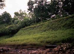
The presence of vegetation mutes or softens the stark visual appearance of conventional mechanically stabilized earth structures and provides potential habitat for riparian wildlife. Overhanging branches of the live brushlayers provide shade for fish and a substrate for insects and other organisms that the fish feed upon. Branches also input leaves and twigs into the stream.
8. HYDRAULIC LOADING
There appears to be little or no published test data for permissible hydraulic loading of VMSE structures. There does exist, however, published data on vegetated coir mats and live brushlayers, respectively, as shown in Table 1. These data can be used to approximate permissible shear stresses and velocities for VMSE. In the case of vegetated coir mats or fabric, the cuttings are inserted through the fabric into the underlying soil, whereas in the case of VMSE, the cuttings are inserted between successive lifts of wrapped earth. In either case, the presence of the vegetation acts to either help anchor the netting in place or to slow velocities adjacent to the netting interface.
Accordingly, upper bound values in Table 1 can be used to estimate allowable shear stresses and velocities for VMSE, particularly when the vegetation is fully established.
TABLE 1: Limiting shear stress and velocity levels
for selected soil bioengineering treatments
(adapted from Fischenich, 2001).
Treatment Type |
Limiting Velocity |
Limiting Shear Stress |
Live fascines |
0.37 0.94 (1.2 3.1) |
29 39 (6 8) |
Coir roll |
0.9 1.5 (3 5) |
39 (8) |
Vegetated coir mat |
1.2 2.4 (4 8) |
46.4 (9.5) |
Live brush mattress (initial) |
0.1 1.2 (0.4 4.1) |
19.5 (4) |
Live brush mattress (established) |
1.2 2.5 (3.9 8.2) |
58.6 (12) |
Brush layering (initial/established) |
0.1 2.0 (0.4 6.5) |
58.6 (12) |
Live willow stakes |
0.64 0.94 (2.1 3.1) |
14.6 48.8 (3 10) |
9. COMBINATION OPPORTUNITIES
A VMSE structure is itself the epitome of a combined approach, i.e., a union between conventional, mechanically stabilized earth on the one hand and brushlayering, a soil bioengineering technique on the other. However, the technique can also be used in conjunction with other techniques, particularly resistive techniques, designed primarily to protect the bank toe, (see Techniques: Vegetated Riprap and Rootwad Revetments) and redirective techniques (see Techniques: Bendway Weirs, Spur Dikes, and Vanes). If excessive seepage daylights from or exits the bank, then a vertical drainage course can be interposed between the bank and the VMSE structure (see Technique: Chimney Drain).
10. ADVANTAGES
Since the inert fabric wraps or geosynthetic tensile inclusions provide reinforcement and mechanical stabilization, they permit much steeper slopes to be constructed than would be possible with live brushlayers alone. Brushlayering treatment by itself is normally restricted to slopes no steeper than 1V:2H. VMSE, on the other hand, can be constructed with a slope as steep as 1V:0.5H. The vegetation shields the fabric against damaging UV radiation, and provides visual and riparian habitat benefits. In addition, when live brushlayers are used, they provide secondary reinforcement, both from the stems themselves, and from adventitious rooting along their imbedded lengths. A little recognized benefit of the brushlayers is the role they play as horizontal drains that favorably modify the groundwater regime (Gray & Sotir, 1996; Ghiassian et al., 1997) in the vicinity of the slope face, thereby improving stability against mass slope failure. This benefit is not realized in the case of standard geotextile or geogrid sheet or layer reinforcements that are used alone.
11. LIMITATIONS
A VMSE structure must be constructed during the dormancy period to insure good vegetative propagation and establishment. Alternatively, the live cuttings may be harvested during dormancy, and placed in temporary cold storage until they ready for use during an out-of-dormancy period, viz., during the summer months (Gray & Sotir, 1996). The latter recourse increases the unit cost of the technique. Materials procurement is more demanding, and installation more complex, because of the blending of two distinct methods, viz., conventional MSE and live brushlayering, into a single approach. Costs will also be more than brushlayering used alone, because of the added expense of the geotextile and the additional labor required to handle and construct the wraps. VMSE streambank structures must be constructed during periods of low water because of the need to excavate and backfill a trench with rock in the streambed to provide a stable foundation (see Figure 1).
12. MATERIALS AND EQUIPMENT
Vegetation: Select long branches of native tree species that are capable of vegetative propagation. Willows (Salix spp) are the most commonly used plant material, because they generally root well from cuttings. Alder, cottonwood (Populus deltoides), and dogwood (Cornus spp) can also be used effectively, particularly when mixed in with willow. The length of the branches will vary depending upon the desired depth of reinforcement, but they should be long enough to reach the back of an earthen buttress placed against a streambank while protruding slightly beyond the face (refer to Figure 1). The diameter of the live cuttings will also vary depending on their length, but typically should range from 19 to 51 mm (¾ to 2 in) at their basal ends.
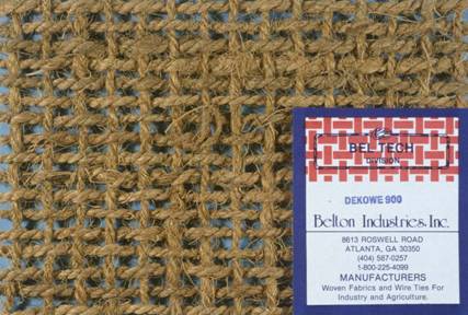
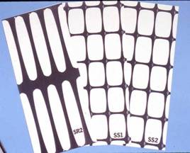
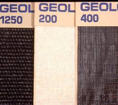
Fabric/Geotextile/Wire Wrap: The inert construction materials consist primarily of either natural geofabrics, such as coir netting (Figure 4) or synthetic, polymeric geogrids and geotextiles (Figures 5 and 6). The latter are more durable and have a higher allowable unit tensile resistance; the former are visually less stark and can retain moisture helpful to vegetative establishment. Welded wire can also be used as reinforcement, and can be PVC or zinc coated. As with most biotechnical structures, the vegetation is intended to provide long-term stability. The designer also needs to consider material longevity, durability, and resistance to abrasion/corrasion. Please see Racin & Hoover (2001) for more information. Coir fabric or netting comes in various grades that have different size openings and unit tensile resistances. Polymeric geogrids likewise come with different size openings and tensile resistance values. In the case of synthetic geogrids, the shape of the openings also plays a role, and can endow a geogrid with anisotropic strength properties. Unit tensile resistances and other properties for a wide variety of geotextiles and geogrids, both natural and polymeric, can be found in several trade association publications and user manuals (IFAI, 2002). Vinyl coated wire may be the longest lasting, followed by synthetic geogrids, and then coir and other biodegradable fabrics. The synthetic geogrids in Johnson Creek have lasted 10 years.
|
|
|
|
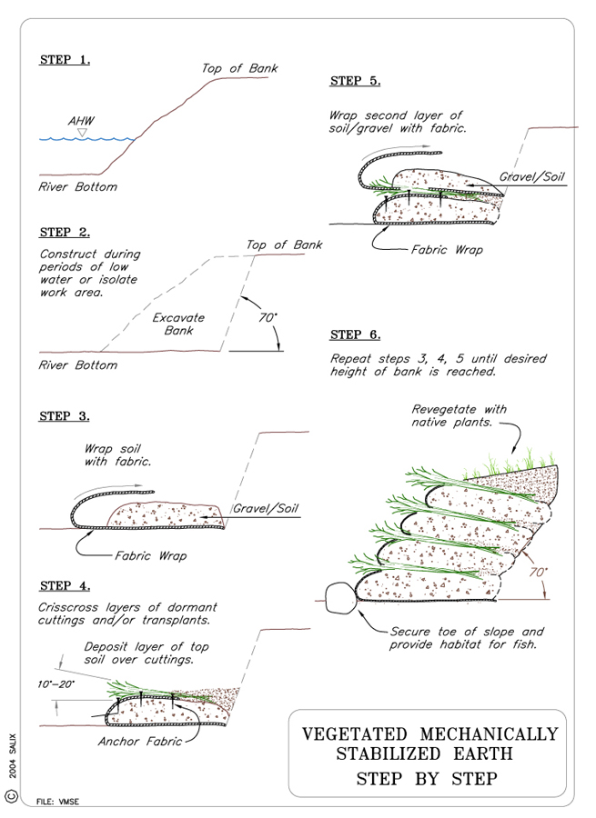
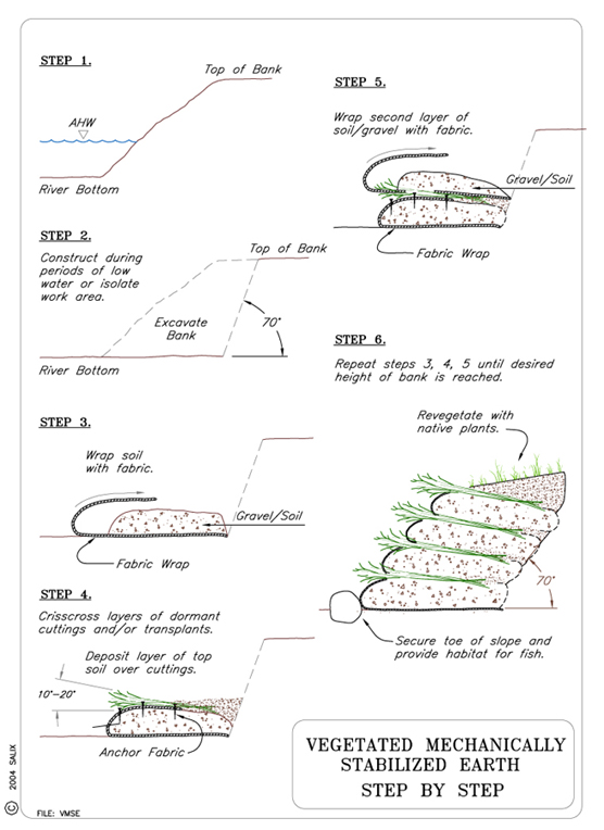
13. CONSTRUCTION / INSTALLATION
A VMSE installation begins at the base of the slope and proceeds upwards. A series of schematic drawings illustrating the installation procedures step by step are shown in the typical drawing. The structure should be supported on a rock toe or base and be battered or inclined at an angle of at least 10 to 20° to minimize lateral earth forces. It is critical that factors such as scour depth be determined for each particular project and be incorporated into project design.These guidelines are not meant to replace or disregard the abundance of available engineering data, equations, or design protocol. The following guidelines and procedures apply:
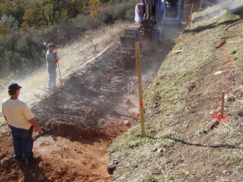
1. Excavate a trench to a competent horizon below the likely depth of scour (see Special Topic: The Key to Stability is the Key), and backfill it with rock to provide a base for the VMSE structure. The top surface of the rock should be inclined with the horizontal to establish the desired minimum batter angle for the overlying structure.
2. Construct an earthen structure reinforced with either polymeric geogrids (or coir fabric) and live brush on top of the rock base. For this purpose, select geogrids or fabric rolls with a minimum roll width of 4 m (13 ft) (see Figure 8) and unit tensile strength predetermined from a stability analysis that takes into account the height and slope angle of the reinforced, earthen buttress fill (see Design Guidelines).
3. Place select fill material on the geogrid (or fabric) and compact it in 7.5 cm (3 in) lifts to a nominal thickness ranging from 30 to 76 cm (12 to 30 in). Thinner lifts are used at the base of the structure, where shear stresses are higher. Temporary batter boards may be required at the front face to confine the select fill during the installation process and to form an even face. When geogrids are used, burlap strips at least 1.2 m (4 ft) wide can be inserted between the earthen fill and the geogrids at the front face to contain the fines and prevent initial raveling of the fill through the apertures in the geogrid.
4. The geogrid or fabric sheet should be allowed to drape down or protrude beyond the front edge of each underlying lift of earthen fill to create at least a 0.9 m (3 ft) overlap when it is pulled up and over the next lift. The exposed sections of geogrid or fabric layers are pulled up and over the faces of the fill layers (refer to typical drawing) and staked in place. The geogrids should be pulled as uniformly as possible before staking to develop initial tension in the geogrid or fabric. A tractor or winch pulling on a long bar with hooks or nails along its length works well for this purpose. The tensioned geogrid overlap sections should be secured in place using wood construction stakes spaced every 0.9 m (3 ft).
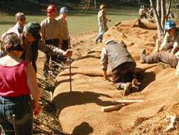
5. Layers of live cut branches are then placed criss-crossed atop the underlying wrapped soil lift (see Figure 9). 25-50 mm (1-2 in) of topsoil should be mixed in with the cut branches. The top soil can be placed beforehand or spread over the top of a brushlayer. Up to three (3) layers of live, cut branches interspersed with 25-50 mm (1-2 in) of topsoil can be placed in this manner.
6. The process is repeated with succeeding layers of earth fill, live brush and geogrids (or fabric) until the specified height or elevation is reached.
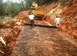
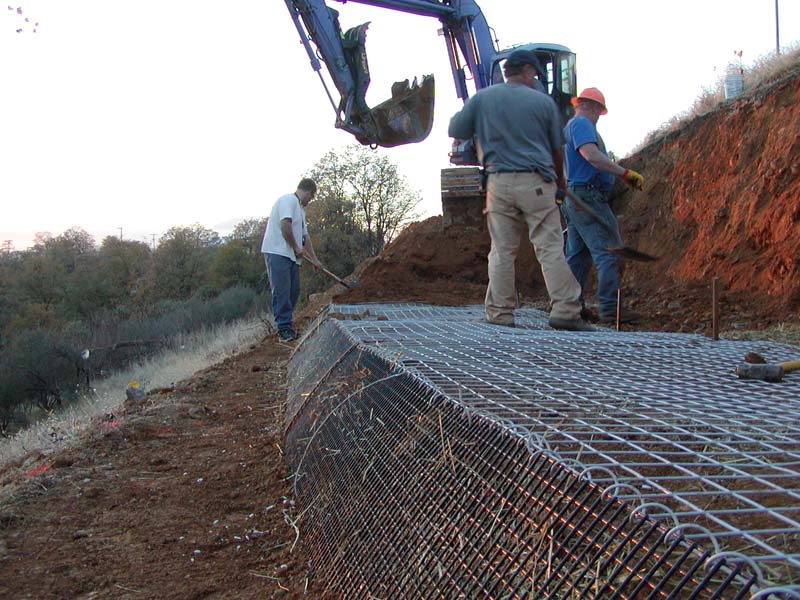
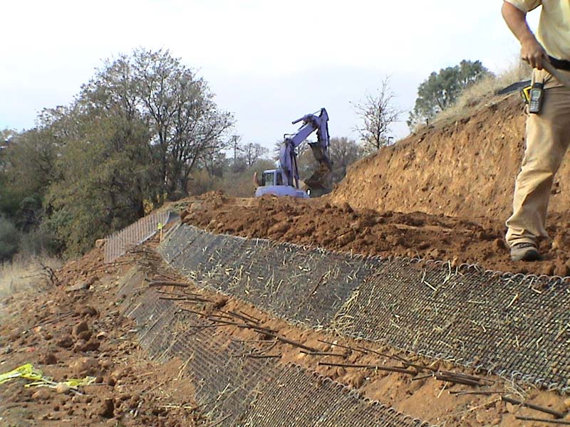
Figure 7. Geogrid roll being spread out prior to placing lifts of compacted soil
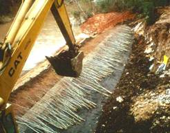
Figure 8. Placement of cut brushlayer atop geogrid wrapped soil lifts
The recommended earthen lift thickness between geogrid (or fabric) layers depends on various soil and site variables, properties of the reinforcements, and desired safety factor. The maximum vertical spacing and imbedded length of successive geogrid or reinforcement layers are determined from the specified safety factor, slope angle, soil shear strength, allowable unit tensile strength, and interface friction properties of the reinforcement layer (see Design Guidelines). Photos showing appearance of a low VMSE structure during and after construction are shown in Figures 9 and 10.
|
|
Figure 9. Low VMSE structure under construction using coir netting for wraps. |
Figure 10. VMSE structure after construction and establishment of live cutting. |
14. COST
Costs for VMSE structures are likely to be on the high end of environmentally-sensitive bank protection measures because of both design/construction complexity and material acquisition costs. In addition, site-specific considerations such as access also have a significant influence. Material acquisition costs depend on the type of fabric material selected, i.e., whether natural fabric, synthetic geotextile, or polymeric geogrid. Installed unit cost ranges for different fabric materials are shown in Table 2.
TABLE 2: Installed unit costs for
different fabric materials
(adapted
from Washington State, 2003)
Fabric Materials |
Cost per m2 (yd2) |
Woven Coir Fabric |
$2.40 $3.60 ($2.00 $3.00) |
Nonwoven Coir |
$1.20 $2.40 ($1.00-$2.00) |
Nonwoven Geosynthetic |
$0.60 $0.84 ($0.50-$0.70) |
Biodegradable Geotextile Fabric |
$3.36 $3.60 ($2.80-$3.00) |
An order-of-magnitude cost estimate for VMSE can be made from relative cost comparisons for different biotechnical bank protection techniques, as shown in Table 3. Costs are shown for brushlayers and soil reinforcement, respectively. These cost comparisons are based on various bank treatments installed primarily in Washington State between 1995 and 2000. Costs are for materials and construction and do not include design or post-construction components of the project. VMSE treatments will cost more than live brushlayering used alone because of the presence of geotextile or geogrid reinforcements, and their material acquisition costs. Note that soil reinforcement costs differ significantly, most likely because of varying material costs for different types of fabric or geogrid reinforcing materials.
TABLE 3: Installed unit costs for biotechnical bank
protection techniques
(adapted
from Washington State, 2003)
Fabric Materials |
Unit of Measure |
Unit Cost |
Woody Plantings (@ 0.9m (3 ft) spacing) |
Hectare ( Acre ) |
$62-$74 ($25-$30) |
Herbaceous Cover |
Hectare ( Acre ) |
$17-$37 ($7- $15) |
Soil Reinforcement |
Linear m (linear ft) |
$164-$1312 ($50-$400) |
Coir Logs |
Linear m (linear ft) |
$26-$98 ($8- $30) |
Bank Reshaping |
Linear m (linear ft) |
$33-$148 ($10-$45) |
Fascines |
Linear m (linear ft) |
$26-$66 ($8- $20) |
Brushlayers and Mattresses |
Linear m (linear ft) |
$121-$164 ($37-$50) |
15. MAINTENANCE / MONITORING
There are no compelling maintenance requirements in the case of VMSE installed along a streambank. The vegetation should establish successfully without irrigation requirements given the proximity to water. Monitoring should consist of inspecting the geogrids (or fabric) for signs of breakage or tearing from scour damage or possibly from excessive tensile stresses due to higher than expected lateral earth pressures. Signs of uncontrolled seepage, such as weeping or wet spots in the structure, should also be noted. Finally, the site should be examined for possible signs of flanking erosion, which must be addressed with ancillary protective measures lest the flanking threaten the integrity and effectiveness of the VMSE structure itself.
16. COMMON REASONS / CIRCUMSTANCES FOR FAILURE
No known instances of failure have been published. The most likely causes of a hypothetical failure, however, would be the following:
Inadequate primary reinforcement from the inert tensile inclusions (fabric or geotextile), i.e., improper vertical spacing or lift thickness, insufficient allowable unit tensile resistance in the selected fabric or geotextile, too short an embedment length, etc., for the given soil and site conditions, viz., slope height, slope angle, and soil shear strength properties,
Failure to properly consider seepage conditions and install adequate drainage measures, e.g., chimney drain behind VMSE structure, and
Inadequate attention to construction procedures and details.
As with all resistive, shoreline protective structures, flanking is always a potential problem.
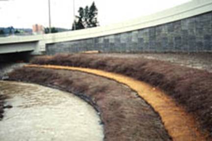
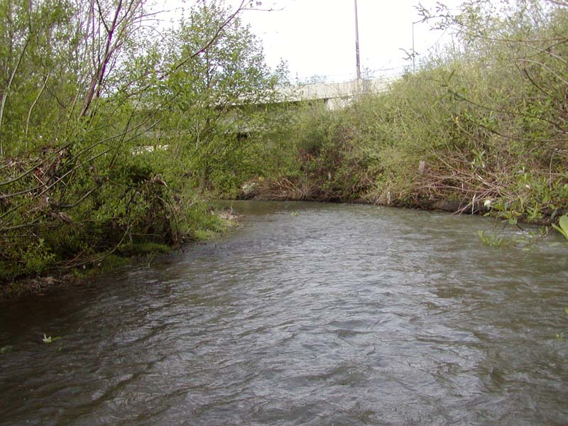
17. CASE STUDIES AND EXAMPLES
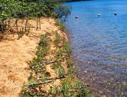
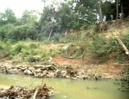
The Oregon Department of Transportation realigned a section of Johnson Creek in order to widen a bridge and complete highway construction. The realignment shortened the creek by approximately 20%, thereby increasing its gradient. Riprap was installed on the streambanks up to the ordinary high water elevation in the outside bends, and the banks above were stabilized with vegetated mechanically stabilized earth. Live siltation was installed on the lowest floodplain berm adjacent to the sub-channel to provide cover for waterfowl and overhanging cover for fish, and the upper bank was protected with a brush mattress.
 |
 |
|
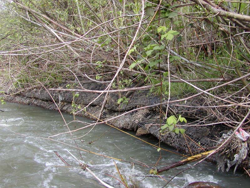
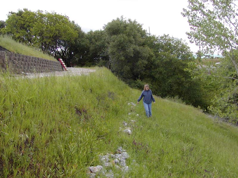
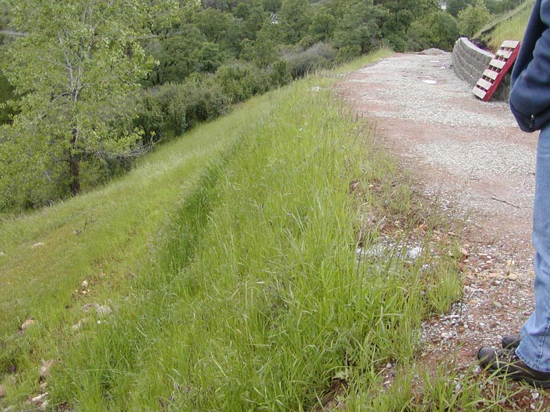
May 2003 almost 10 years
after construction.
The rock toe on the outer bend was undercut, however the vegetation was well
established.
|
 |
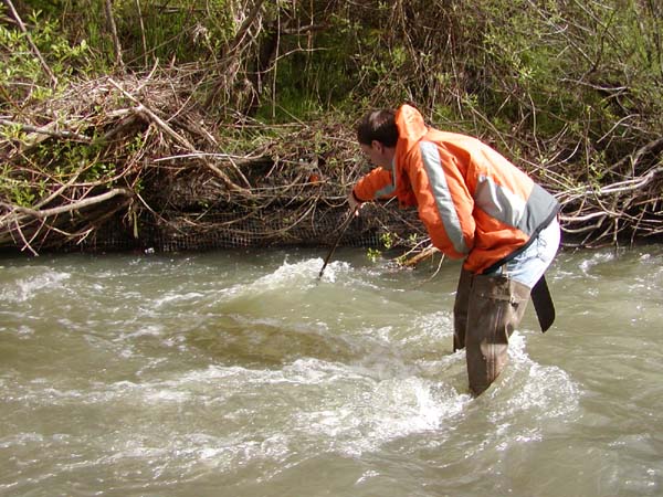 |
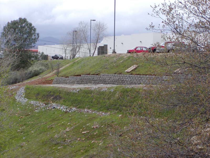
| After 10 years the riprap
toe has eroded and the banks are "undercutting",
however the geogrids have survived and the bank has well established
riparian cover. |
|
VMSE has been successfully employed in a number of instances along streambanks in different parts of the country. The case study described herein is a good example of the effectiveness of this technique to stabilize and protect a high, steep bank subjected to periodic flooding or inundation. The site in question is located along Buffalo Bayou in Houston, Texas. A detailed description can be found in Gray and Sotir, 1996.
|
|
|
|
|
|
 |
 |
|
Brushlayering was installed at the bottom for additional geotechnical
stabilization and aesthetics. |
 |
 |
|
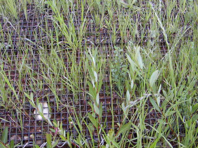
Vegetated MSE after 5 month growth, native grasses
and willow sprouts predominate. |
 |
 |
Vegetated MSE after 5 month growth. |
|
 |
|
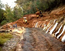
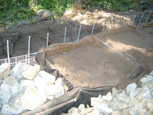
FHWA Highway Project, Umpqua River, Oregon
 |
 |
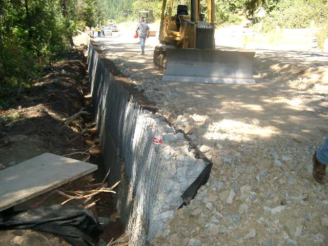
Vegetated mechanically
stabilized earth wall, FHWA project, Umpqua River, Oregon. Photo
by J. McCullah. |
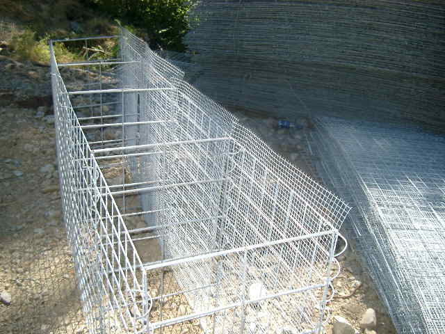
The wire baskets used here are similar to gabions
but manufactured specifically for retaining walls. Note the fine wire
screen used for face. |
 |
 |
|
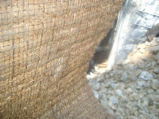
Polypropylene-coir composite,
was pre-impregnated with native seed and placed along the face of
the wire retaining wall. Umpqua River, Oregon. |
Please visit the Photo Gallery for more pictures.
18. RESEARCH OPPORTUNITIES
Some uncertainty exists at present as to the exact permissible shear stresses and velocities for VMSE interfaces. Performance results during high water conditions indicate that VMSE can withstand hydraulic loadings at least equal to those listed in Table 1 for either vegetated coir mats or live brushlayers alone. Additional research would also be helpful on the nature of the interaction between roots and fabric and root architecture/distribution in VMSE structures.
19. REFERENCES
Bonaparte, R.; Holtz, R. D. & Giroud, J.P. (1987). Soil reinforcement design using geotextiles and geogrids. Geotextile Testing and the Design Engineer, ASTM STP 952, J.E. Fluet, Jr., ed., American Society for Testing and Materials, Philadelphia, 1987, pp. 69-116
Fischenich, J. C. (2001). Stability thresholds for stream restoration materials. EMRRP Technical Notes Collection (ERDC-TN-EMRRP-SR-29), U.S. Army Engineering Research and Development Center, Vicksburg, MS. (pdf)
Ghiassian, H., Gray, D.H., & Hryciw, R. (1997). Seepage considerations and stability of sandy slopes stabilized by anchored geosynthetics. Proceedings, Geosynthetics '97, St. Paul , MN , IFAI, pp. 581-593.
Gray, D.H. & Sotir, R. (1992). Biotechnical stabilization of a highway cut. Journal of Geotechnical Engineering (ASCE), Vol. 118, No. GT10, 1992.
Gray, D. H. & Sotir, R. (1996). Biotechnical and Soil Bioengineering Slope Stabilization. John Wiley and Sons, New York, N. Y.
IFIA (2002). Specifiers Guide Vol. 20, No. 9, Industrial Fabrics Association Intl., Roseville, MN, December 2002.
Koerner, R. M. (1998). Designing with Geosynthetics. 4th edition, Prentice Hall, 1998, 761 pages.
Mitchell, J.K, & Villet, W.C. (1987). Reinforcement of Earth Slopes and Embankments, Natl. Coop Hwy Research Program Report #290, TRB-NRC, Washington, DC, 320 pp
Racin, J. A. & Hoover, T. P. (2001). Gabion Mesh Corrosion: Field Study of Test Panels and Full-scale Facilities. (Final Report No. FHWA-CA-TL-99-23) State of California Department of Transportation, Division of New Technology and Research, Sacramento, CA. (pdf)
USDA Soil Conservation Service. (1996). Chapter 16: Streambank and Shoreline Protection. Part 650, 210-EFH, Engineering Field Handbook, 88 pp. (pdf)
Washington Dept of Fish & Wildlife (2003). Integrated Streambank Protection Guidelines, published in co-operation with Washington Dept. of Transportation and Washington Dept. of Ecology, April 2003. (Chapter 6 pdf) http://www.wa.gov/wdfw/hab/ahg/ispgdoc.htm