| CHIMNEY DRAIN |
 |
| CHIMNEY DRAIN |
|
1. CATEGORY
4.0 – Slope Stabilization
2. DESIGN STATUS
Level II
3. ALSO KNOWN AS
Drainage blanket, curtain drain, sloped sheet drain, and strip drain.
4. DESCRIPTION
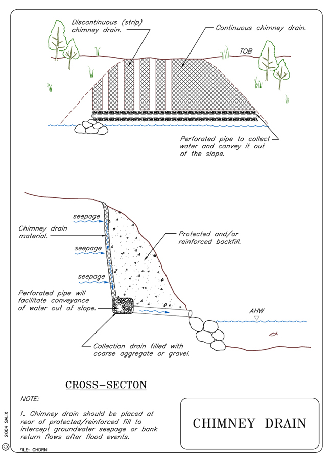
A Chimney Drain is a subsurface drainage course placed between a natural slope (or streambank) and an earthen buttress fill or other retaining structure (e.g., log cribwall). The buttress fill may be either a standard earthen brushlayer fill or a Vegetated Mechanically Stabilized Earth (VMSE) fill. A drainage blanket, sloped sheet drain, and strip drain are types of subsurface drainage courses. Typically a Chimney Drain is a near vertical drain that feeds into a collection system at its base whereas a sloped sheet drain is inclined back at an angle. A subsurface drain may be continuous across the slope, or it may consist of discontinuous drainage strips that are placed against the natural slope at periodic intervals. The drainage course may consist of 1) natural graded aggregate, 2) a non-woven geotextile with good in-plane drainage capacity, or 3) a geo-composite drain. A geo-composite drain is comprised of a filter fabric that is bonded to or wrapped around a pervious core.
5. PURPOSE
The purpose of a subsurface drain is to provide an efficient and effective way for water contained in a slope to drain. A chimney drain intercepts sub-surface seepage that would otherwise saturate and destabilize an earthen buttress placed against a streambank. A subsurface drainage layer increases slope stability by decreasing soil pore water pressure. The brushlayers in the earthen buttress also act as horizontal drains that help to relieve pore water pressure and prevent saturation of the fill. Any subsurface drain layer must have good water transmission properties.
6. PLANNING
Useful for Erosion Processes:
Toe erosion with upper bank failure Scour of middle and upper banks by currents Local scour Erosion of local lenses or layers of noncohesive sediment Erosion by overbank runoff General bed degradation Headcutting Piping Erosion by navigation waves Erosion by wind waves Erosion by ice and debris gouging General bank instability or susceptibility to mass slope failure
Spatial Application:
Instream Toe Midbank Top of Bank
Hydrologic / Geomorphic Setting
Resistive Redirective Continuous Discontinuous Outer Bend Inner Bend Incision Lateral Migration Aggradation Conditions Where Practice Applies:
Subsurface drains are rarely installed as a stand-alone treatment (Washington State, 2002) instead they are normally used in combination with other treatments such as brushlayer fills or vegetated mechanically stabilized earth fills (See Techniques: Live Brushlayering and Vegetated Mechanically Stabilized Earth). Subsurface drainage should be considered if any or all of the following conditions exist:
A drainage layer (either a continuous blanket drain or discontinuous strip drains) should be installed whenever a poorly drained, earthen buttress fill or other retaining structure is placed against a streambank that has emergent seepage or groundwater flow exiting the bank. If the fill is constructed of granular material that is already well drained then a drainage blanket may be not necessary.
Rapid drawdown (bank return flows following flood events)
Signs of slumping, seeps, or soil creep in the bank
Poorly drained soils in the bank
Complexity:
Chimney Drains are relatively easy to install, especially if pre-manufactured geocomposite strip drains or non-woven geotextiles with good in-plane drainage capacity are used.
Design Guidelines / Typical Drawings:
A continuous chimney or curtain drain can be constructed using either a lofty, non-woven, needle punched fabric (geotextile) with good in-plane drainage capacity, or alternatively, by using a geo-composite drainage blanket (see Special Topic: Role of Geotextiles). Information on the in-plane discharge capabilities of fabric filters and equivalent sand layers compared with clean aggregate layers can be found in Cedergren (1989).
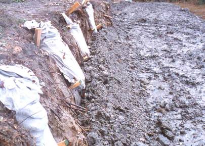
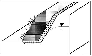
A discontinuous chimney drain or strip drain consists of vertical drain elements that are placed at periodic intervals (Gray and Sotir, 1996) against the natural slope (or streambank) as shown in Figures 1 and 2. As a general rule, the drain strips should cover at least one-third of the face area of the slope. A higher density of drain strips can be concentrated in areas of known or heavy seepage. Use of discontinuous strips allows easier root penetration from the live brushlayers in the buttress fill into the natural slope behind the buttress.
Figure 1. Close up view of strip chimney drains placed between streambank and brushlayer fill.
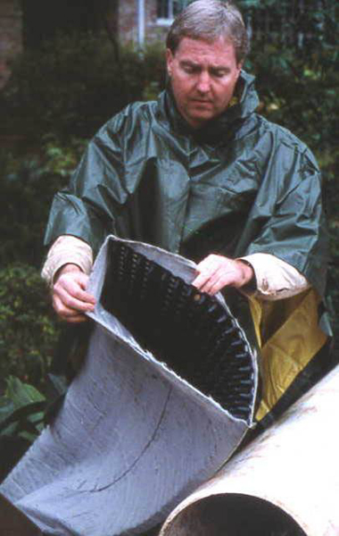
Figure 3. Strip drain comprised of filter fabric wrapped around a polymeric "egg carton" core. The fabric filters out fines while the core permits unimpeded flow of water.
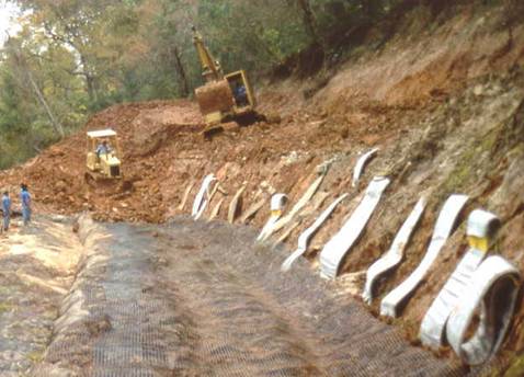
Figure 2. Reinforced earthen brushlayer fill protected against saturation from bank seepage by vertical strip drains or chimney drains.
Discontinuous or strip chimney drains can be fabricated by wrapping a filter fabric around a flat pervious core as shown in Figure 3. The pervious core can be fabricated from polymeric sheets with an "egg carton" shape or alternatively, from semi-rigid, three-dimensional polymeric webs, e.g., Enkamat® or Tensar® turf reinforcement mats.
7. ENVIRONMENTAL CONSIDERATIONS / BENEFITS
Groundwater that seeps into and saturates an earthen buttress can destabilize and negate the effectiveness of the buttress. Placement of a chimney drain behind the buttress prevents this from happening. Interception and collection of this seepage behind the crest of the slope not only corrects the problem, it does so in a non-intrusive and visually transparent manner. No major regrading of the streambank itself is required other than grubbing and smoothing of the slope before placement of the drain. Slope stabilization allows development of a well-vegetated riparian zone, with attendant benefits to aquatic and terrestrial habitats.
8. HYDRAULIC LOADING
Hydraulic loading is not a factor in the design/installation of chimney drains because they are placed behind a buttress fill and are not exposed to shear or tractive stresses of streamflow. The only hydraulic consideration is that the drain has sufficient in-plane drainage capacity to handle the seepage flows that are intercepted by the drain.
9. COMBINATION OPPORTUNITIESChimney drains can be used with earthen Live Brushlayer fills or VMSE fills, and Live Cribwalls. Anytime a poorly-drained earthen structure is placed against a streambank to support or armor the bank, a drainage course or chimney drain should be placed behind the structure. "Poorly-drained" implies that the buttress structure has insufficient permeability to pass or transmit water exiting from the bank without the buildup of excess pore water pressure at the contact interface.
10. ADVANTAGES
Chimney drains are relatively easy to install, hidden from view, very effective for intercepting lateral seepage, and critical for insuring that earthen buttress fills do not become saturated and hence vulnerable to mass stability failure.
11. LIMITATIONS
Chimney drains are susceptible to clogging from fines that are carried into the drain in the seepage stream. Graded aggregate filters and geocomposite drains must be selected carefully, using appropriate filter criteria to insure that water can pass through the drain while at the same time excluding fines. Lofty, non-woven geotextiles may lose a large fraction of their in-plane drainage capacity if they are subjected to large compressive stresses.
12. MATERIALS AND EQUIPMENT
The main drain materials consist of either 1) graded natural aggregate, 2) a lofty, non woven geotextile with good in-plane drainage capacity, or 3) strip drains composed of a filter fabric wrapped around a porous core. The term "lofty" in this case refers to greater thickness as result of higher void space, e.g., wool fleece, felt or cotton wool batts. These material or drainage products can normally be placed by hand or with the aid of a small backhoe. A geotextile or geo-composite drain is much easier and faster to place than a graded aggregate drainage course. Other materials that may be required include synthetic (geotextile) filter fabric and perforated pipe.
13. CONSTRUCTION / INSTALLATIONChimney drains should be placed against a prepared slope surface that is relatively smooth and free of vegetation and other surface projections. The drains should discharge into a collection drain at their base. Collection drains are linear structures oriented parallel to the bank face at the bank toe. The collection drain can be constructed of coarse aggregate or gravel. Placement or embedment of a perforated pipe within the aggregate improves the conveyance efficiency of the collection drain (see Technique: Trench Drain for pipe sizing and design guidelines). Finally, collection drains must discharge collected water into the stream in an efficient manner. Discharge can be accomplished by routing or tying the collection drain into a longitudinal stone toe protection system. Alternatively, collection drains can discharge into a stone-and-gravel filled sump at the toe of the bank (Washington State, 2003).
14. COST
Material costs make up most of the total cost of chimney drains. Polymeric drainage geo-composites or blankets run approximately $4 /m2 ($0.40 /ft2). A lofty, non-woven, needle-punched geotextile with good in-plane drainage capacity runs approximately $0.70 /mv ($0.06 /ft2) for geotextile with unit weight of 200 g/m2 (6 oz/yd2). The installation cost will be site dependent. The material cost of filter gravel (placed) runs from $52 – 78 /m3 ($40-60 /yd3), river gravel runs $52 – 104 /m3 ($40-80 /yd3) and pit run rock ranges from $39-52 /m3 ($30-40 /yd3). Material costs for a bank 5 m (16 ft) high with drain strips covering one-third of the face area of the slope would be about $12 /m ($6.67 /ft) of bank.
15. MAINTENANCE / MONITORING
Subsurface drains cannot easily be accessed once installed. A possible way to monitor the performance of chimney drains is to check the outflow from the pipe that drains the rock drainage layer beneath a buttress fill into which the chimney drains discharge. If there is steady emergent seepage from a streambank, this exit drain should flow continuously. On the other hand, if emergent seepage only tends to occur as bank return flow after flood events, the exit drain should flow only after flood waters recede. The effectiveness of subsurface drains in dewatering a bank can be monitored indirectly by examining for signs of seepage and/or slumping/sliding at the bank face or surface of a protective earthen buttress.
16. COMMON REASONS / CIRCUMSTANCES FOR FAILURE
The limitations of drains cited previously are the most common reasons for failure. Loss of drainage capacity from clogging or compression of a drain can lead to the saturation and buildup of pore pressure in a buttress fill or the slope (streambank) behind it. Either of these conditions can lead to a mass stability failure of the buttress and/or streambank.
17. CASE STUDIES AND EXAMPLES
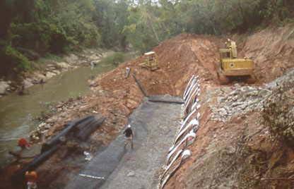
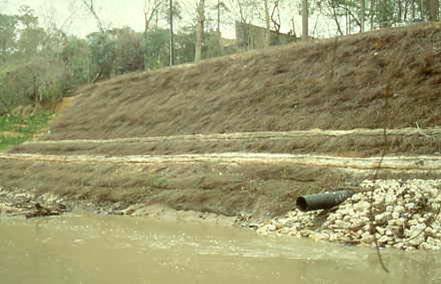
Vertical strip drains were used as part of a streambank stabilization/repair project on a bayou near Houston, Texas (Gray and Sotir, 1996). The instability of a high, over-steepened bank was aggravated by the presence of fine sands and emergent seepage from the bank of between 0.75 to 7.5 m3 (200 to 2000 gallons) per day. The interception and diversion of this seepage was essential to successful stabilization of the streambank. A Vegetated Mechanically Stabilized Earth (VSME) fill was placed against the streambank. The fill, which had a steep face sloped at a gradient of 1V:0.5H, was constructed upon a foundation of wrapped concrete rubble installed in a 2 m (7 ft) deep trench, as shown in Figure 4. The concrete rubble also served as a basal drainage layer.Because continued seepage and saturation of the fill would have substantially reduced the factor of safety against a mass stability failure, it was necessary to install appropriate drainage. This was accomplished by using vertical strip or chimney drains at the rear of the fill installed on 1.5 m (5 ft) centers that intercepted and collected the seepage water and conducted it into a concrete rubble drain beneath the fill. Water collected in the basal drain was in turn collected in and discharged to the bayou via pipes located at the upstream and downstream ends of the project as shown in Figure 5.
Figure 4. Concrete rubble foundation drain constructed beneath VMSE fill that was placed against streambank. Vertical strip drains discharge into this basal drain.
Figure 5. Final appearance of stabilized streambank. Seepage water collected in the basal drain was collected in pipes and discharged into the bayou.18. RESEARCH OPPORTUNITIES
There several research opportunities associated with Chimney Drains. The first is to determine whether a continuous subsurface drain poses a serious impediment to root penetration, and whether discontinuous strip drains would be preferable in this regard. The second is to ascertain to what extent horizontal layers of brush imbedded in a live brushlayer fill enhance chimney drain performance and limit pore water buildup either in the streambank itself or an earthen buttress fill placed against it.
19. REFERENCES
Cedergren, H. R. (1989). Seepage, Drainage, and Flow Nets. John Wiley and Sons, 3rd edition, New York, N. Y.Gray, D. H. & Sotir, R. (1996). Biotechnical and Soil Bioengineering Slope Stabilization. John Wiley and Sons, New York, N. Y.
Washington Dept of Fish & Wildlife (2003). Integrated Streambank Protection Guidelines, published in co-operation with Washington Dept. of Transportation and Washington Dept. of Ecology, June 2003. (Chapter 6 pdf) (Appendix L pdf) (Appendix H pdf) http://www.wa.gov/wdfw/hab/ahg/ispgdoc.htm (April 2003)