
| ROLE OF GEOTEXTILES
AND NATURAL FABRICS |
|
Geotextile is defined as "A permeable geosynthetic comprised solely of textiles. Geotextiles are used with foundation, soil, rock, earth, or any other geotechnical engineering-related material as an integral part of a human-made project, structure, or system," (ASTM D 4439). Geotextiles are composed of ultraviolet (UV) stabilized polymeric fibers, filaments or yarns that are typically made from polypropylene (PP) and polyester (PET). Geotextiles can be divided into two major classes: woven and nonwoven. In each class, there are several subgroups, depending on the manufacturing procedure and fiber configuration. Table 1 shows the types of geotextiles within each class (Koerner, 1998). In addition, there are varying unit weights available for each type of geotextile. Every December, Geotechnical Fabrics Report (GFR) magazine (http://www.ifai.com/magazines/gfr.php3) publishes a specifier's guide that contains an extensive tabulation of geotextile products and basic properties provided by manufacturers.
TABLE 1: Types of geotextiles
| Nonwoven Geotextiles | |
| Heat-bonded continuous filaments Needled punched continuous filaments Needled punched staple fibers |
|
| Woven Geotextiles | |
| Monofilament Multifilament Slit film |
|
MATERIAL SPECIFICATIONS
Although some states have their own geotextile specifications, the American Association of State Highway and Transportation Officials (AASHTO) has formulated a unified geotextile specification for different applications. The specification, AASHTO M288-96, provides for three different classifications. The classifications are essentially a list of strength properties meant to withstand varying degrees of installation survivability stresses.
Class 1 For severe or harsh survivability conditions where there is a greater potential for geotextile damage.
Class 2 For typical survivability conditions; this is the default classification to be used in the absence of site specification information.
Class 3 For mild survivability conditions.
Table 2 shows the basic requirements for the above three classes of geotextiles. Accompanying the main table (Table 2), each general type of application has additional requirements for permittivity, apparent open size and ultraviolet resistance, as shown in Tables 2-a to 2-e.
TABLE 2: AASHTO M288 Geotextile strength property requirements
Property |
Test Method (ASTM) |
Classification* |
|||||
Class 1 |
Class 2 |
Class 3 |
|||||
Elongation < 50% |
Elongation > 50% |
Elongation < 50% |
Elongation > 50% |
Elongation < 50% |
Elongation > 50% |
||
| Grab Strength, lb, (N) |
D 4632 |
315 (1400) |
202 (900) |
247 (1100) |
157 (700) |
(800) |
(500) |
| Sewn Seam Strength§, lb (N) |
D 4632 |
270 (1200) |
182 (810) |
223 (990) |
142 (630) |
(720) |
(450) |
| Tear Strength, lb (N) |
D 4533 |
112 (500) |
79 (350) |
90 (400) |
56 (250) |
(300) |
(180) |
| Puncture Strength, lb (N) |
D 4833 |
112 (500) |
79 (350) |
90 (400) |
56 (250) |
(300) |
(180) |
| Burst Strength, psi, (kPa) |
D 3786 |
508 (3500) |
247 (1700) |
392 (2700) |
189 (1300) |
(2100) |
(950) |
| Permittivity (1/s) |
D 4491 |
Minimum property requirements for permittivity, AOS and UV stability
are based on geotextile application: Table 2-a: for subsurface filtration Table 2-b: for separation Table 2-c: for stabilization of soft subgrade Table 2-d: for erosion control Table 2-e: for temporary silt fences |
|||||
| Apparent Open Size (mm) | D 4751 |
||||||
| Ultraviolet Stability (%) |
D 4355 |
||||||
§ When sewn seams are required. Overlap seam requirement are application specific.
TABLE 2a: AASHTO M288 Subsurface Filtration Application
Default Geotextile Class Class 2* |
||||
Property |
Test Method |
Percent In-Situ Soil passing # 200 sieve (0.075 mm) |
||
< 15 |
15 to 50 |
> 50 |
||
Permittivity§ |
D 4491 |
0.5 |
0.2 |
0.1 |
Apparent |
D 4751 |
0.43 |
0.25 |
0.22 + |
Ultraviolet |
D 4355 |
50% after 500 hr of exposure |
||
* The Engineer may specify a Class 3 geotextile from Table 2 if conditions are less severe.
§ Performance testing should be considered in problematic soil environments such as non-cohesive silts, gap-graded soils; alternating sand/silt laminated soils; dispersive clays; and/or rock flour.
+ For cohesive soils with a plasticity index greater than 7, geotextile MARV is 0.3 mm.
TABLE 2b: AASHTO M288 Separation Application
Default Geotextile Class Class 2* |
||
Property |
Test Method |
Requirement |
Permittivity§ (1/s) |
D 4491 |
0.02§ |
Apparent |
D 4751 |
0.60 |
Ultraviolet |
D 4355 |
50% after 500 hr of exposure |
* The Engineer may specify a Class 3 geotextile from Table 2 if conditions are less severe.
§ Default value. Permittivity of the geotextile should be greater than that of the soil (Ψg > Ψs). The Engineer may also require the permeability of the geotextile to be greater than that of the soil (kg> ks).
TABLE 2c: AASHTO M288 Stabilization Application
Default Geotextile Class Class 1* |
||
Property |
Test Method |
Requirement |
Permittivity (1/s) |
D 4491 |
0.05§ |
Apparent |
D 4751 |
0.60 |
Ultraviolet Stability (%) |
D 4355 |
50% after 500 hr of exposure |
* The Engineer may specify a Class 2 or 3 geotextile from Table 2 if conditions are less severe.
§ Default value. Permittivity of the geotextile should be greater than that of the soil (Ψg > Ψs). The Engineer may also require the permeability of the geotextile to be greater than that of the soil (kg> ks).
TABLE 2d: AASHTO M288 Erosion Control Application
Default Geotextile Woven
monofilament - Class 2* |
||||
Property |
Test Method |
Percent In-Situ Soil passing # 200 sieve (0.075 mm) |
||
< 15 |
15 to 50 |
> 50 |
||
Permittivity§ |
D 4491 |
0.7 |
0.2 |
0.1 |
Apparent |
D 4751 |
0.43 |
0.25 |
0.22 |
Ultraviolet |
D 4355 |
50% after 500 hr of exposure |
||
* The Engineer may specify a Class 2 or 3 geotextile from Table 27 if conditions are less severe.
+ The default geotextile selection is appropriate for stone weights not exceeding 100 kg (220 lbs), stone drop height of less than 1 m (3.3 ft), and the geotextile protected by a 150 mm (6 in) thick soil bedding layer. More severe applications require an assessment of geotextile survivability based on a field trial section and may require a geotextile with higher strength properties.
§ Performance testing should be considered in problematic soil environments such as non-cohesive silts, gap-graded soils; alternating sand/silt laminated soils; dispersive clays; and/or rock flour.
For cohesive soils with a plasticity index greater than 7, geotextile MARV is 0.3 mm.
TABLE 2e: AASHTO M288 Temporary Silt Fence Application
Property |
Test Method |
Supported |
Unsupported Silt Fence |
|
Elongation = 50%+ |
Elongation < 50%+ |
|||
Maximum post spacing |
1.2 m |
1.2 m |
2.0 m |
|
Grab Strength, lb (N) |
D 4632 |
|
|
|
Permittivity§ (1/s) |
D 4491 |
0.05 |
0.05 |
0.05 |
Apparent |
D 4751 |
0.60 |
0.60 |
0.60 |
Ultraviolet |
D 4355 |
70% after 500 hr exposure |
||
* Silt fence support shall consist of 14 gage steel wire with a mesh spacing of 150 mm x 150 mm (6 in x 6 in) or prefabricated polymeric mesh of equivalent strength.
+ As measured in accordance with ASTM D 4632.
§ These default filtration property values are based on empirical evidence with a variety of sediments. For environmentally sensitive areas, a review of previous experience and/or site or regionally specific geotextile tests should be performed.
PHYSICAL PROPERTIES
The basic physical properties of geotextiles are specific gravity, mass per unit area, and thickness. Table 3 shows the standard tests used to evaluate these properties. Of the three physical properties, mass per unit area is most commonly referenced and required by specifications. Specific gravity is governed by the polymer type that is used to manufacturer the geotextile. The specific gravity of PP and PET polymers is approximately 0.91 and 1.3, respectively. The specific gravity of the geotextile may increase slightly, depending on the percentage of carbon black added. The thickness of the geotextile is rarely required in the material specification; however, this parameter is required to convert the permittivity value to permeability in the filtration design.
TABLE 3: Physical properties of geotextiles
Property |
ASTM Method |
Specific gravity |
D 792 |
Mass per unit area |
D 5261 |
Thickness |
D 1777 |
MECHANICAL PROPERTIES
A series of mechanical tests are used to assess the strength of geotextiles, as shown in Table 4. The first four listed in the table are index properties. Geotextile manufacturers require these properties to perform quality control of their products, and many State standard specifications reference these tests; however, index properties are not commonly used in design. Wide width tensile strength, on the other hand, is a performance property that is used in design for reinforcement applications. A 200 mm (8 in) wide specimen is tested using a strain rate of 0.017 mm/sec (0.04 in/min), in order to replicate plane strain condition and slow deformation in the field. Figure 1 shows the general stress-strain response of various types of geotextiles. Strengths at ultimate and 5% strain are reported. When the design requires sewing panels of geotextile in the field, the seam strength should be evaluated. The seam strength is assessed using a 200-mm (8 in) wide specimen with a seam in the middle at a strain rate of 0.017 mm/sec (0.04 in/min). Only the ultimate strength is recorded. In some cases, a percentage of tensile strength (ratio of seam strength to wide width tensile strength) is reported.
Table 4: Mechanical properties of geotextiles
Property |
ASTM Method |
Grab tensile strength (kN) |
D 4632 |
Burst strength (kPa) |
D 3786 |
Tear strength (N) |
D 4533 |
Puncture strength (N) |
D 4833 |
Wide width tensile strength (kN/m) |
D 4595 |
Seam strength (N) |
D 4693 |
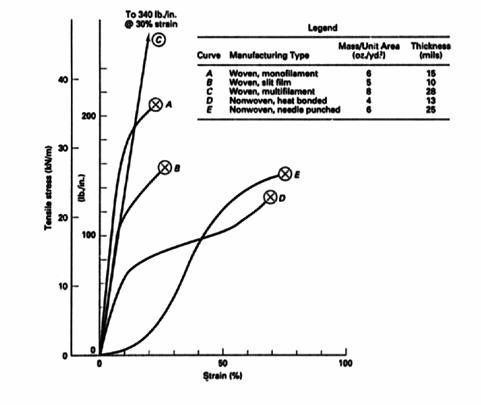
Figure 1. Tensile test response of various geotextiles (Koerner, 1998)
HYDRAULIC PROPERTIES
When geotextiles are used in filtration and drainage functions, hydraulic properties are important. Table 5 shows the two essential hydraulic properties of geotextiles and the corresponding test method. The Apparent Opening Size (AOS), a sieve number defined by the standard, reflects a property also quantified by the O95, the corresponding sieve-opening size in mm. The value is obtained by sieving of known-diameter glass beads through the geotextile. Sieving is done using beads of successively larger diameters until the weight of beads passing through the test specimen is 5% of the weight of beads applied or less. From the percent passing versus glass bead diameter plot, the O95 (mm) is determined, and the corresponding sieve size is the AOS value, as illustrated in Figure 2. The AOS is usually specified as the maximum average roll value or MARV.
TABLE 5: Mechanical properties of geotextiles
Property |
ASTM Method |
Apparent opening size (sieve size) |
D 4751 |
Permeability (m/s) |
D 4495 |
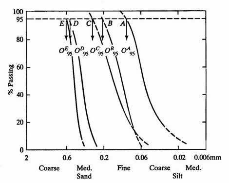
Figure 2. Typical pore size distribution of different types of geotextiles,
(Koerner, 1998)
The permeability of a geotextile is measured by the constant-head test. Due to the compressible nature of fabrics, however, a geotextile-related parameter called permittivity (Ψ) is used. This parameter incorporates the fabric's thickness, as shown in Equation (1).
![]() (1)
(1)
| where: | Ψ= permittivity (1/s), |
| kn = permeability (m/s) (properly called hydraulic conductivity), and | |
| t = thickness of the geotextile (m). |
Permittivity is obtained using the Darcy's formula as shown in Equations (2) and (3).
![]() (2)
(2)
![]() (3)
(3)
| where: | q = flow rate (m2/s), |
| i = hydraulic gradient (dimensionless), | |
| Δh = total head lost (m), and | |
| A = area of the geotextile (m2). |
ENDURANCE PROPERTIES
There are four endurance properties that are potentially significant in erosion
applications: creep, clogging, ultraviolet degradation, and polymer degradation
of the geotextiles.
Creep is defined as the time dependent elongation of a material while under constant load. Geotextiles are generally considered to be creep-sensitive materials, and therefore, elongation under constant load must be addressed in the design of reinforcement applications, such as slope stabilization. Selected creep reduction values to be used in reinforcement applications are given in Table 6.
TABLE 6: Reduction factor against creep deformation for various polymers
Polymer |
Den Hoedt (1986) |
Lawson (1986) |
Task force no. 27 (1991) |
Koerner (1998) |
Polypropylene |
4.0 |
2.5-5.0 |
5.0 |
3.0-4.0 |
Polyester |
2.0 |
1.5-2.5 |
2.5 |
2.0-2.5 |
Polyamide |
2.5 |
1.5-2.5 |
2.9 |
2.0-2.5 |
In filtration applications, soil clogging of geotextiles, particularly nonwoven geotextiles, is a very important issue. It was shown by Carroll (1983) that geotextiles that satisfy soil retention and permeability criteria can still fail by clogging. Soil retention design (which will be discussed in the filter fabric section) is based on limiting the O95 value, or the size of the largest openings. Small opening size is not considered. Clogging is mainly caused by small particles that are trapped in the geotextile matrix, consequently decreasing the permeability. Christopher and Fisher (1992) compiled literature addressing the clogging issue depending on the severity of the application, as shown in Table 7.
TABLE 7: Clogging Criteria (Christopher and Fisher, 1992)
A. Critical/Severe Applications:
|
B. Less Critical/Nonsevere Applications:
|
• For Cu < 3, fabric with maximum opening size from retention criteria should be specified. |
There are three soil/fabric filtration tests that can be used to evaluate the clogging potential of the geotextile. They are long-term flow, gradient ratio and hydraulic conductivity ratio tests. All three tests are performance tests, i.e. using candidate geotextile with site specific soil.
Long-term Test:In the long-term flow test, the flow rate is monitored for 1000 hr. The terminal slope of the flow rate versus time curve is then evaluated as adequate or inadequate for the site (Wayne and Koerner, 1993).
Gradient Ratio:The gradient ratio (GR) test is performed according to ASTM D 5101. The GR value is calculated based on Equation 4. The U. S. Army Corps of Engineers suggests that GR > 3.0 indicates non-acceptable geotextiles for the type of soil under testing.
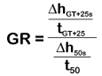 (4)
(4)
| where: | ΔhGT+25s = head change (mm) from the bottom of the geotextile to 25 mm (1 in) of soil above the geotextile |
| tGT+25 = geotextile thickness (mm) plus 25 mm (in) of soil | |
| Δh50s = head change (mm) between 50 mm (2 in) of soil above the geotextile. | |
| t50 = 50 mm (2 in) |
The Hydraulic Conductivity Ratio (HCR) test is performed according to ASTM D 5084. The HCR value is determined based on Equation (5).
![]() (5)
(5)
| Where: | ksg = permeability of soil-geotextile system |
| ks = permeability of the soil |
and typically, HCR values of 0.4 0.8 suggest soil piping may be of concern, and values less than 0.4 may indicate excessive clogging (Williams and Abouzakhm, 1989; Luettich and Williams, 1989).
3. Ultraviolet Degradation
When the photon energy of the UV light exceeds the bond energy of polymers, UV degradation occurs (Hirt and Searle, 1964). All polymers are susceptible to ultraviolet (UV) degradation, but to varying degrees. For geotextiles, the rate of UV degradation is proportional to the specific surface area of the fibers; because specific surface area is high, geotextiles should not be exposed to sunlight for a long period of time. Koerner and Hsuan (1992) suggested the allowable exposure duration for different nonwoven geotextiles as follows:
| Polypropylene (with carbon black) | 14 days |
| Polyester (without carbon black) | 10 days |
| Polyester (with carbon black) | 15 to 30 days |
DeBerardino (1993) has also recommended covering nonwoven PP geotextile within 14 days after deployment. For woven geotextiles, a longer exposure time could be considered depending on the diameter of the filaments. Generally, each State Department of Transportation has its own construction guideline that limits the allowable exposure time of the geotextile.
The current requirement to ensure the minimum UV resistance of geotextiles is based on ASTM D 4355. The targeted geotextile is exposed to a Xenon weatherometer, according to conditions stated in the ASTM D 4355, for 500 hours; the strength retained must be > 70%. Hsuan et al., (1994) have demonstrated that the rate of UV degradation during the exposure period decreased substantially after removal from the UV source.
4. Long-term DegradationAfter the geotextile is placed, the longevity of the polymer should be compatible with the designed lifetime of the erosion system. Degradation mechanisms are fundamentally different for PP and PET, the two common types of polymers used in geotextile. PP is more susceptible to oxidation, whereas PET is more susceptible to hydrolysis. The rate of oxidation degradation of PP depends on oxygen concentration and temperature. The chemical properties of the soil, such as pH, have no effect on the reaction. In contrast, the hydrolysis of PET is highly sensitive to both soil pH and temperature (Hsuan et al., 1993). Since geotextile has not been in use long enough to establish field data, laboratory accelerated tests are used to predict geotextile lifetimes (Elias et al., 1999). Results of lab tests showing the effect of PH on the rate of PET degradation is shown in Figure 3. At a pH below 10, the tensile strength loss is less than 1% per year. However, the PET yarns must consist of a minimum molecular weight of 24,000 and maximum carboxyl end group of 30 mol/g. The test methods to evaluate the two material properties are GRI GG 8 and 7, respectively.

Figure 3 Average rate of PET yarn tensile strength loss in %/yr at 20° C at varying pH values.
On the other hand, the oxidation of PP geotextile involves another group of chemical components called antioxidants. Without antioxidants, PP products are oxidized relatively quickly. All PP geotextiles contain antioxidants to protect the polymer from degradation during the manufacturing process and service duration. However, the type and amount of antioxidants can vary significantly, which subsequently influences the overall lifetime of the geotextile. Currently, research is still directed towards developing a standard index test to assess the amount and type of antioxidant in the PP geotextiles.
REFERENCES
Calhoun, C.C. (1972), Development of Design Criteria and Acceptance of Specification for Plastic Filter Cloth. Technical Report 5-72-7, US Army Corps of Engineers Waterways Experiment Station, Vicksburg, MS.
Carroll, R.G., Jr. (1983). Geotextile Filter Criteria, Engineering Fabrics in Transportation Construction, TRR 916, TRB, Washington, DC, pp. 46-53.
Christopher, B.R. & Fischer, G.R. (1992). Geotextile Filtration Principles, Practices and Problems. Journal of Geotextiles and Geomembranes, Vol. 11. Nos. 4-6, pp. 337-354.
Christopher, B.R. & Holtz, R.D. (1985). Geotextile Engineering Manual, Report No. FHWA-TS-86/203. US FHWA, Washington, D.C.
Christopher, B.R. & Holtz, R.D. (1989). Geotextile Construction and Design Guidelines, HI-89-050, Prepared for FHWA, Washington, D.C.
DeBerardino, S. (1993). A Geosynthetics UV Stability Needs to be Addressed, Geotechnical Fabrics Report, Vol. 11, No. 6, Published by IFAI, Roseville, MN
Den Hoedt, G. (1986). Creep and Relaxation of Geotextile Fabrics. Journal of Geotextiles and Geomembranes, Vol. 4, No. 2, p. 83-92.
Elias, V., Salman, A., Juran, I. , Pearce, E., & Lu, S., (1999).Testing Protocols for Oxidation and Hydrolysis of Geosynthetics, Publication No. FHWA-RD-97-144.
Fischer, G.R., Christopher, B.R. and Holtz, R.D. (1990). Filter Criteria based on Pore Size Distribution. Proc. of the 4th Intl. Conf. on Geotextiles, The Hague, The Netherlands, Vol. I. pp. 289-294
Giroud, J.P. (1982). Filter Criteria for Geotextiles. Proc. of 2nd Intl. Conf. on Geotextiles, Las Vegas, Nevada, Vol. I., IFAI, Roseville, MN, pp. 103-108.
Haliburton, T.A., Lawmaster, J.D., & McGuffey, V.E. (1982). Use of Engineering Fabric in Transportation Related Applications. FHWA Training Manual FHWA Contract No. DTFH-80-C-0094.
Halse, Y., Koerner, R.M. & Lord, A.E.Jr., (1987). Filtration Properties of Geotextiles under Long Term Testing. Proc, ASCE/PennDOT Conf. Advances in Geotechnical Eng. Harrisburg , PA : PennDOT, pp. 1-13.
Hirt, R.C. & Searle, N.Z. (1964). Wavelength Sensitivity or Activation Spectra of Polymers. Regional Technical Conference, Society of Plastics Engineers, Washington , D.C. pp. 286-302.
Hsuan, Y.G., Koerner, R.M. & Lord, E., (1993). A Review of the Degradation of Geosynthetic Reinforcing Materials and Various Polymer Stabilization Methods. Geosynthetic Soil Reinforcement Testing Procedures, ASTM STP 1190, S.C. Jonathan Cheng, ed.
Hsuan, Y.G., Koerner, R.M., & Soong, T.Y., (1994). Behavior of Partially Ultraviolet Degraded Geotextiles. Fifth Int. Conf. on Geotextiles, Geomembranes and Related Products, Singapore, September, pp. 1209-1212.
Koerner, R. M. (1999). Designing with Geosynthetics. 4th edition, Prentice Hall, 1998, 761 pages.
Koerner, R.M. and Hsuan, Y.G. (1992). Timely Cover with Respect to Geosynthetics. The GRI Newsletter/Report, Vol. 6, No. 2, Published by GSI, Folsom, PA.
Lawson, C.R. (1986). Geosynthetics in Soil Reinforcement. Proc. Symp. On Geotextiles in Civil Engineering, Institution of Engineers Australia, Newcastle, pp. 1-35.
Luettich, S.M. & Williams, N.D. (1989). Design of Vertical Drains using the Hydraulic Conductivity Ratio Analysis. Proc. Geosynthetics '89, IFAI, Roseville, MN, pp. 95-103.
Task Force #27. (1991). Guidelines for the Design of Mechanically Stabilized Earth Walls. AASHTO-AGC-ARTBA Joint Committee, Washington D.C.
Wayne, M.H. & Koerner, R.M. (1993). Correlation Between Long Term Flow Testing and Current Geotextile Filtration Design Practice. Proc. Geosynthetics'93, IFAI, Roseville, MN, pp. 501-517.
Williams, N.D. & Abouzakhm, M.A. (1989). Evaluation of Geotextile-Soil Filtration Characteristics using the Hydraulic Conductivity Ratio analysis. Journal of Geotextiles and Geomembranes, Vol. 8, No. 1, pp. 1-26.