| SPUR DIKES |
|
1. CATEGORY
1.0 – River Training
2. DESIGN STATUS
Level I
3. ALSO KNOWN AS
Bank barbs, deflectors, groins, wing dikes, transverse dikes, permeable dikes,
hard points, or jetties. Other variations include earth core dikes with vegetation,
stone spurs capped by reinforced earth prisms (known as live booms), debris
groins, log, or log and rock wing deflectors.
4. DESCRIPTION
Spur dikes are stone spurs that extend into the stream from the bank to minimize
erosion by forcing flow away from the bank. Two to five structures are typically
placed in series along straight or concave bank lines where flow lines are roughly
parallel to the bank. Spur Dikes differ significantly from Vanes and Bendway
Weirs with how they are oriented (angled) and how they are intended to be used.
 |
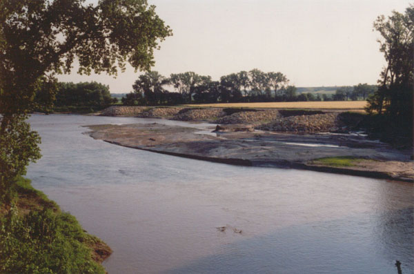 |
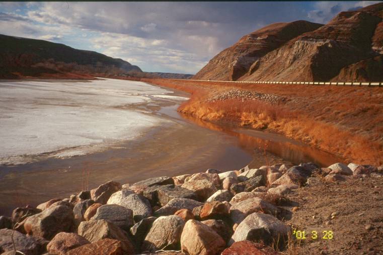
| Spurs used to protect highway in Alberta, Canada. Photo courtesy of J. McCullah |
Spurs designed and
built by Kansas DOT on the Little Blue River. Photo courtesy of Phil Balch, The Watershed Institute. |
Earth core dikes are spurs constructed with a soil core armored by a layer of stone and an embedded stone toe on the upstream side. Stone spurs capped with a prism of earth reinforced with live fascines are referred to as "live booms". The earth prism is constructed with alternating layers of live fascines and soil. The imbedded fascines act as internal reinforcements. Vegetation may be planted on the crests of earth core dikes or natural succession may occur on stone structures that are overtopped frequently enough to accrete sediments, but are above normal stages during the growing season.
Spurs can also be constructed from natural materials, such as Large Woody Debris (LWD), and are designed to provide biological benefits and habitat restoration. Using the classical spur design criteria and methods, the placement of LWD can be designed to achieve optimum benefit for both aquatic habitat and bank protection (see Technique: Large Woody Debris Structures).
5. PURPOSE
Spurs are used in river engineering to minimize bank erosion and lateral stream
migration, thereby protecting infrastructure such as roads, bridges, and dwellings.
It is clear that the physical characteristics of spurs and the resulting flow
modifications result in desirable habitat benefits. Redirecting and concentrating
flow patterns away from the banks results in key features for aquatic habitat:
Deep pools at the tips;
Cover for fish, especially when spurs are combined with Large Woody Debris, Willow Posts and Poles or Live Brushlayering;
Protection of eroding banks, and resultant reduced sediment loads;
Single and opposing wing deflectors are used to concentrate water into a selected area of the channel to create scour, thereby accelerating the flow. Wing deflectors can create quiet water resting places for upstream migrating spawners. Opposing wing deflectors are built to deflect the flow to create a scour pool, and sort spawning gravel. They are best used in long uniform glides and riffles to diversify habitat and create velocity shear zones. (CA Fish and Game, 1998)
6. PLANNING
Useful for Erosion Processes:
Toe erosion with upper bank failure Scour of middle and upper banks by currents Local scour Erosion of local lenses or layers of noncohesive sediment Erosion by overbank runoff General bed degradation Headcutting Piping Erosion by navigation waves Erosion by wind waves Erosion by ice and debris gouging General bank instability or susceptibility to mass slope failure
Spatial Application:
Instream Toe Midbank Top of Bank
Hydrologic / Geomorphic Setting
Resistive Redirective Continuous Discontinuous Outer Bend Inner Bend Incision Lateral Migration Aggradation Conditions Where Practice Applies:
Spur dikes are most commonly used in shallow, wide streams with moderate to high transport of suspended bed material. Shallow channel depths reduce the required height of structures. A wide channel provides room for the channel alignment and geometry to adjust, and a heavy supply of suspended bed material during high flows which accelerates the rate of induced deposition (Biedenharn, Elliott & Watson, 1997).
Spur dikes are often used on large rivers (for example, the Little Blue River in Kansas and the Red River in Alberta, Canada) to increase depth for navigation, in addition to improving channel alignment and stabilizing banks. They can be used to stabilize the channel alignment upstream and downstream of revetted bends, since the shallower depths, moderate velocities, and less concentrated drift loads upstream and downstream of bends are more suitable for in-channel structures than bends (Biedenharn, Elliott & Watson, 1997).
Spur dikes can be used on smaller, higher gradient streams, but act more as jetties in such situations by diverting or redirecting flow, as opposed to providing channel roughness elements (Washington, 2003).
Dikes can be used where establishment of riparian vegetation is a high priority. Initial plantings and natural establishment of native species can be supplemented by later plantings on sediments deposited within and behind the structures, or by sloping and vegetating the upper bank slopes once lower bank stability has been attained (Biedenharn, Elliott & Watson, 1997).
Spur dikes are usually used on outer banks especially along long radius bends. As bend radius decreases, spacing must decrease, and the required number of dikes soon reaches a point where the method is no longer cost-effective.
Complexity:
Low to moderate.
Design Guidelines / Typical Drawings:
A review of design guidelines is found in HEC-23 (Lagasse et al., 1997) and Biedenharn et al. (1998). Design guidelines for habitat restoration are also documented in Watershed Habitat Rehabilitation Procedures, Watershed Restoration Technical Circular No. 9 (Slaney and Zaldokas, 1997).Key design variables and considerations include:
Limits of protection
Spur length and spacing
Crest angle and crest elevation
Type of spur (e.g. rock, woody debris with rock, earthen boom), and its susceptibility to scour
Design also includes plan layout of groups ("fields") of structures along eroding banklines.
Limits of Protection
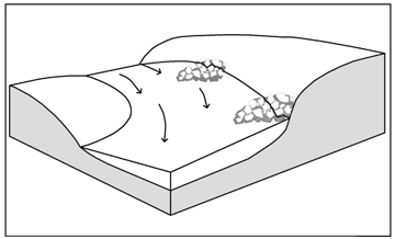
The figure below illustrates the suggested limits of protection. It is noted that protection typically extends further upstream than necessary, and not far enough downstream (Lagasse et. al., 1997). While the core of maximum velocity follows the thalweg at low flows, it shortens its path by cutting across a point bar at high flows so that the region of high shear stress along the outside bank shifts downstream as discharge increases towards bankfull. Therefore, the maximum bed scour and bank erosion are likely to be observed in the downstream part of the bend, or even downstream of the bend at high discharges (Simon and Sentürk, 1976; Bathhurst, 1979).
Figure 1. The hatched area shows suggested extent of spur dike field. From USACE (1981).Spur Length and Spacing
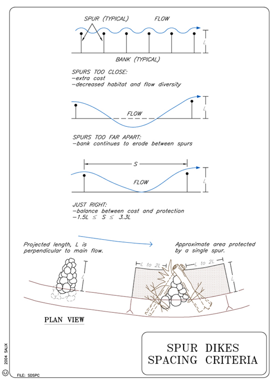
The length of the spur will vary widely, but typically are most effective when they are 20% or less than bankfull channel width (Lagasse et al., 1995 (2001 pdf)). Other workers suggest spur length should be about one third the channel width at bankfull stage (D. Shields, personal communication, 2003).
Flow leaves the tip of the groin at an angle 17° bankward of direct downstream flow in flume studies (Lagasse et al., 1995 (2001 pdf)). The next groin should be positioned to intercept this redirected flow; and in many situations, this will correspond to a spacing of 3.3 times the length of the groin from bank to tip (Washington, 2002). Other workers suggest spur spacing should be about 1.5 times their length (D. Shields, personal communication, 2003). Note that actual spacing must be determined based on site conditions. Spacing decreases as bend radius decreases, so dikes become less economically attractive in low-radius bends than in straighter reaches. It should also be noted that when spur spacing is decreased, habitat and flow diversity decreases, as the dike field acts more like a riprap revetment (Washington, 2003).
Crest Angle and Width
In general, the crest angle may vary from perpendicular to approach flow to ~15° upstream (or at a 75° angle with the approach flow). Crest width should be two to three times as great as the diameter of the largest stone (2-3 D100). In practice, all of these parameters vary considerably with site condition (see the aforementioned references for details). Spurs placed on sand beds devoid of gravel may subside as sand is washed from beneath the stone (Shields, Cooper, Knight, 1995). Crest widths may be increased to provide additional stone for launching into downstream scour holes if such scour is anticipated.
Crest Elevation
Crest elevations vary widely and designers should consult the following references: HEC-23 (Lagasse et al., 1997), Biedenharn et al. (1998), and Slaney and Zaldokas (1997). Spur dikes are generally built higher than Bendway Weirs, but should not exceed bank height, as erosion in overbank areas could cause flanking at high stream stages (Washington, 2003). The longevity of aquatic habitats associated with dikes on the Lower Mississippi River relative to those on the Missouri River is attributed to the lower crest elevations (relative to high flow stages) used on the Mississippi (Shields 1995).
Extent of Scour
Kuhnle et al. (1999 and 2002) presented empirical formulas for predicting spur scour hole depth and volume as a function of flow depth and dike dimensions. Scour hole size increases with dike length. Scour hole volume is also greater for dikes angled 45° upstream (at an angle of 135° with the downstream bankline) than for other alignments (Kuhnle et al., 2002). See guideline on Vanes for structures that point upstream at a greater angle. Structures angled upstream also redirect overtopping flow away from the protected bank (Biedenharn et al., 1998).
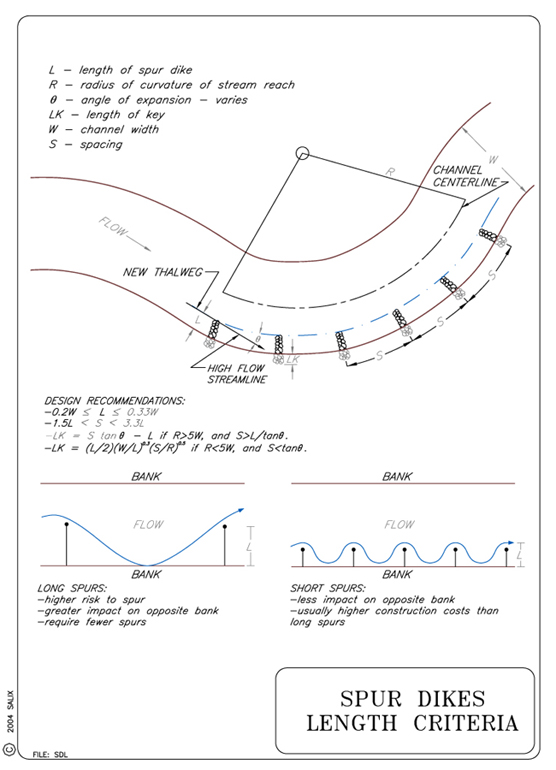
Spur Dikes should be keyed into the bank to prevent flanking. The United States Department of Agriculture (USDA) Soil Conservation Service (SCS) (1996) suggests a minimum key length for small streams of 2.4 m (8 ft) or 4(D100), whichever is greater. However, this is a minimum and keyways should be sized based on site conditions. Some formulas are provided below to assist with calculations (LaGrone, 1995).
When the radius of curvature is large (R>5W) and the spacing is greater than L/tan (Θ), then:
LK = S tan (Θ) – L
When the radius of curvature is small (R<5W) and the spacing is less than L/tan (Θ), then:
LK = L/2 (W/L)0.3 (S/R)0.5
Where: R = radius of curvature LK = length of key W = channel width S = spacing between the spurs Θ = expansion angle defined in the length criteria drawing below L = length of spur measured from bankline to spur tip Live Booms
Spur dikes capped with a prism of earth that supports vegetation are called live booms. When constructing live booms, rock is used below the annual high water line, and compacted soil reinforced with embedded, criss-crossing live fascines is used above the rock. When the desired elevation is reached, the structure can be covered with a layer of armor rock that is then joint planted (See Technique: Live Staking). In addition to the environmental benefits provided by the incorporation of vegetation directly into live booms, the use of an earthen core in the dike may be advantageous in locations where rock or stone is in short supply.
Live boom constructed with compacted soil embedded with Live Fascines. Buffalo Bayou, Houston, TX, courtesy of Doug Hanford
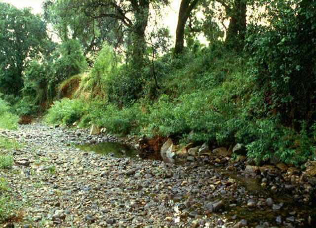
Vegetated Spur or live boom constructed at 20 m intervals to protect oak trees and the Redding Arboretum land.
Sulphur Creek, Redding, CA, 1998
Sulphur Creek, Redding, CA
Sulphur Creek, Redding, CA
Sulphur Creek, Redding, CA
Sulphur Creek, Redding, CA
7. ENVIRONMENTAL CONSIDERATIONS / BENEFITS
Deflectors,
wing dams and other spur-type structures create geometrically complex water/shore
interface conditions that in degraded streams can mimic the stable
substrate, velocity shelter, and cover provided by large woody debris accumulations
and tree falls. In addition, spurs create scour holes that may provide stable
pool habitats or
the ability to
flush finer sediments from spawning gravels. They provide fish rearing habitat,
holding areas for adult fish and velocity refugia. Submerged portions
of stone structures increase aquatic habitat diversity by providing attachment
habitat for benthic
organisms, scour holes
at the riverward ends, and slack water and sediment deposition for burrowing
organisms between successive structures. When desirable, spurs can be configured
to induce higher sedimentation along channel margins. Disturbance to terrestrial
habitats is usually minimal because little upper bank clearing is required. Dikes
create minimal interference with existing overbank drainage patterns and riparian
access to the waterway.
Aesthetic impacts are
beneficial once the structures are covered with vegetation, and the vegetation
can be useful for wildlife habitat. These benefits are enhanced in the case
of live booms that incorporate vegetation directly into the dike structure
itself (Gray and Sotir, 1996). Structures along deeper rivers may provide a
number of recreational benefits, including fishing access, boat launching,
and boat mooring. Structures can be notched to increase the amount of low-velocity
habitat contiguous to the main channel on large, stabilized river systems,
but notches sometimes induce rather than minimize backwater sedimentation
(Shields, 1983; 1988).
Sedimentation and erosion in response to structures is usually most rapid
during the first few high flow seasons following construction, and then typically
exhibits mild fluctuation about an equilibrium condition
(Shields, 1995).
8. HYDRAULIC LOADING
Permissible shear and velocity for spur dikes is related to the size of rock used in construction. Other factors, such as the angularity of the stone, the thickness of the layers of stone, and the angle at which the faces of the stone structure are constructed also come into play. Detailed guidance for sizing stone for bed and bank stabilization structures is beyond the scope of this guideline, and many approaches are available (See Special Topic: Designing Stone Structures). However, the Maynord (1995) equation gives a D50 stone size for an angular stone riprap revetment of 0.875 m (2.9 ft) if the near-bank vertically-averaged velocity is 3.5 m/s (11.5 ft/s), and flow depth = 1 m (3.3 ft), and stone is placed on a bank slope of 1V:1.5H. Use of riprap larger than this is unusual.
9. COMBINATION OPPORTUNITIES
Willows
(Salix spp) or other flood tolerant woody vegetation is sometimes planted
in high densities between adjacent structures, and grass and forb seed mixtures
may be planted to stabilize the bank until the woody vegetation becomes well
established. Vegetation may be planted on the crests of earth core dikes or natural
succession may occur on stone structures that are overtopped frequently enough
to accrete sediments, but are above normal stages during the growing season.
Volunteer vegetation may be prolific in humid regions with adequate seed sources.
Woody vegetation should be used on middle and upper banks, but avoided at the
toe.
Spur Dikes, Bank Barbs and LWD deflectors are sometimes used with Longitudinal Stone Toe with Spurs (See Technique: Longitudinal Stone Toe with Spurs).
10. ADVANTAGES
Spur dikes provide a means to modify the channel alignment, are well suited to an incremental construction approach, and are amenable to the establishment of woody vegetation. Also, many designs use locally-available material.
Spur dikes also offer the opportunity for incorporating a wide variety of environmental features. They may increase the diversity of aquatic and terrestrial habitat, although subsequent sediment deposition may be detrimental to shallow water habitat (Biedenharn, Elliott & Watson, 1997). In terms of physical aquatic habitat, spurs are usually superior to continuous, resistive measures (Shields, Cooper, Testa, 1995).
11. LIMITATIONS
If the channel is very deep, spurs are usually less cost-effective for bank protection than riprap blanket or other types of revetment. This is because the volume of stone required to build a dike increases rapidly with the height of the structure. Dikes may not be used to protect banklines if some additional erosion between structures cannot be tolerated, as some "bank scalloping" usually occurs after construction until a state of equilibrium is attained.
Spur dikes become less economically attractive in low-radius bends than in straighter reaches, because of the decreased spacing in low-radius bends.
Channel capacity at high flow is decreased initially when dikes are constructed, although the channel will usually adjust by forming a deeper, though narrower, cross-section. The ultimate result may even be an increase in conveyance capacity; however, the extent of the adjustment cannot always be predicted reliably, even with physical or numerical models (Biedenharn, Elliott & Watson, 1997).
Spurs that are designed and constructed with LWD should include biotechnical techniques that will promote the long-term establishment of riparian vegetation.
12. MATERIALS AND EQUIPMENT
Angular stone used for spur dikes should be sized based on suggestions in the hydraulic loading section. Sizing guidelines for self-launching stone, which will self-adjust to scour, can be found in the special topic on Self-Launching Stone. LWD, if specified, should be naturally occurring therefore it should be available nearby.
Heavy equipment will be needed to place the stone and excavate key trenches.
13. CONSTRUCTION / INSTALLATION
Protection of the existing riparian zone is critical; therefore, access and staging areas need to be carefully planned. Turbidity may be a significant problem during construction, therefore construction techniques which reduce turbidity shall be employed, such as: minimize disturbance, use tracked excavators, winches or hand labor, work during low-flow periods, use dewatering or stream diversion techniques, or use stream isolation techniques (McCullah, 2004).
In case of sudden high flow events, each spur should be constructed by excavating and filling the key trench first. Then the riverward part of the structure may be completed by dumping or placing stone. Some workers favor placing stone in vertical lifts to allow gradual adjustment of the adjacent channel boundary. In rare circumstances it may be necessary to divert flow or dewater the channel to complete spur placement.
Vegetated spurs or live booms can be excavated into the bank and also below the channel bottom. Place rock around the edges to the elevation of annual high water stage (bankfull stage). LWD or rootwads, if specified, must be keyed and dipping into the bank and anchored with large boulders and/or anchors. The core of the spur can be filled with native soil/gravel with intermittent levels of brushlayering or pole planting. Continue the sequence of rock face, soil core, and vegetation until the design height is reached.
LWD spurs or wing dikes are constructed similarly but the trenches into the banks must be of sufficient depth to anchor the structures. Place large boulders, native material and biotechnical practices (brushlayering, willow poles) in the core.
14. COST
On the Missouri River, construction costs for earth core dikes and hard points
varied from $220 to $750 per linear m ($65 to $236 per ft) of structure,
or $33 to $308 per m ($10 to $94 per ft) of bank line protected in1984 dollars.
Costs for spurs are typically about the same as for riprap blanket.
In 2000, on the Keogh River in British Columbia, the total cost of one large
(6 m projection
(19.7 ft))
LWD spur with ballast and anchoring was CAN$6,000. Note
that this cost includes one half hour of Sikorsky S-61 helicopter time at CAN$1,800.
15. MAINTENANCE / MONITORING
The structures should be monitored at least once per year, and after all events with a return interval greater than two years. Monitoring should continue for at least 5 years (Washington, 2003). Structures should be checked for subsidence and loss of stone, especially from the crest and riverward tip.
Erosion should be monitored on the streambank between spurs and around the perimeter of the spur itself. If significant streambank erosion is noted, rock can be placed just upstream and downstream of spur keys to prevent the possibility of flanking (Washington, 2003).
16. COMMON REASONS / CIRCUMSTANCES FOR FAILURE
The most common causes of spur failure are undermining and outflanking by the stream (bank erosion around and behind the structure). These problems occur primarily in alluvial streams that experience wide fluctuations in the channel bed (Lagasse et al., 1997). If downstream scour holes are anticipated, provide more stone for self-launching by building a wider crest width. The additional rock can then be sacrificed without changing the crest elevation. Outflanking can be prevented by properly keying in the structure.
17. CASE STUDIES AND EXAMPLES
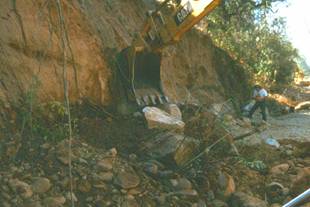
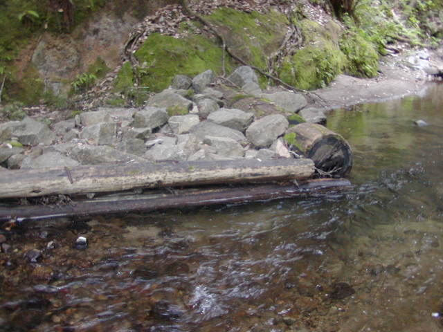
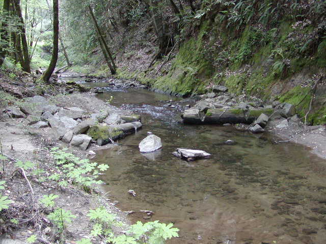
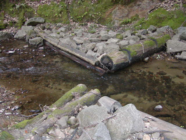
One case study article covers some basic technical theory in the design and layout of spurs (debris groins) for bank protection as it follows the implementation at the Keogh River clay bank site below Hwy 19 near Port Hardy, British Columbia (Feduk, 2001).
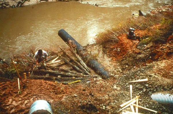
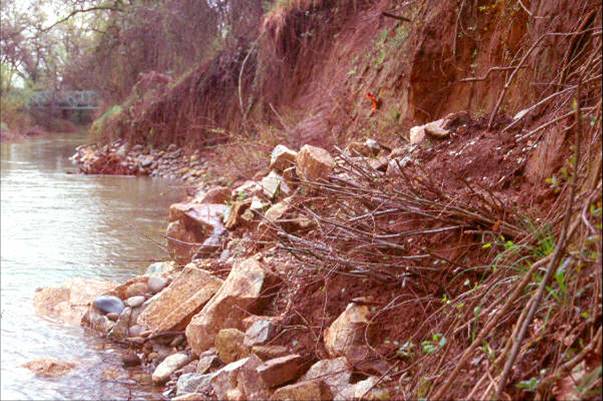
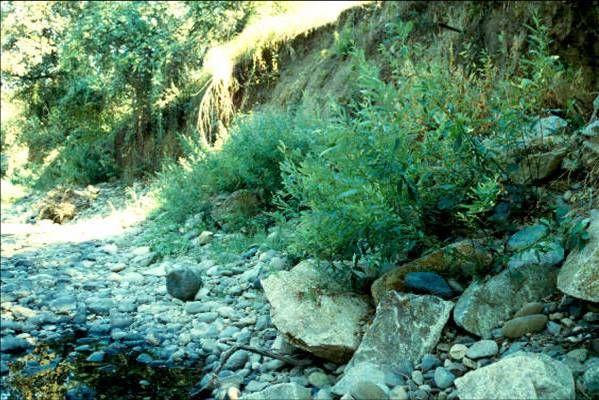
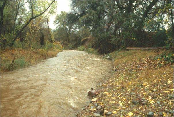
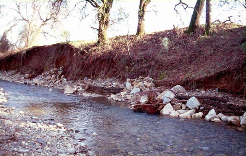
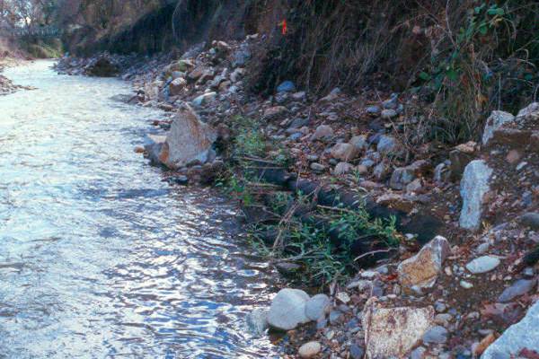
A series of vegetated rock deflectors (spurs) were installed along a high, eroding bank in Sulphur Creek, Redding, California in 1996. Bank migration was threatening large oaks located at the top of the bank. The spurs had crest lengths of 2-3 m (6.5–10 ft), were approximately 2 m (6.5 ft) high at the bank. These structures experienced severe El Nino storm events the first winter before the willow had a chance to establish. Discharge was approximately 28 m3/s (1,000 cfs), and velocities were estimated greater than 2.4 m/s (8 ft/s). No bank erosion was observed, and the thalweg was effectively relocated an average 3 m (10 ft) streamward of the bank .
|
|
Spur dikes during installation
on Sulphur Creek, 1996 |
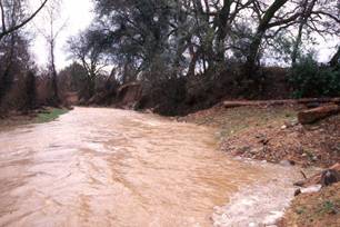
Spur dike deflecting flow into the center of the channel during high
flows the winter after construction. |
 |
 |
 |
 |
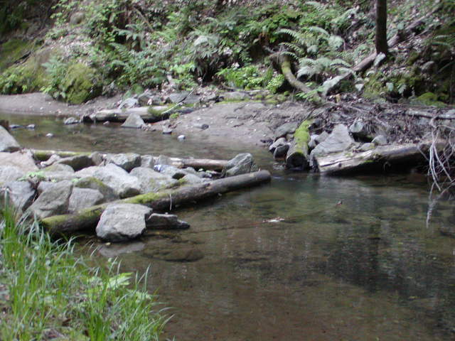
| Wing deflectors
on Zayante Creek, Santa Cruz County, CA |
|
Please visit the Photo Gallery for more pictures.
18. RESEARCH OPPORTUNITIES
More quantitative algorithms are needed for selecting spur dike design parameters
(crest length, angle, width and spur spacing) in order to achieve design goals
of channel alignment control, bank protection, and pool habitat creation.
An analysis of scour potential for different substrates with regards to redirective
techniques is needed.
19. REFERENCES
Bathurst, J. C. (1979). Distribution of Boundary Shear Stress in Rivers. Adjustments
of the Fluvial System. In Rhodes, D. D. & Williams, G. P. (Eds.), Adjustments
of the Fluvial System (pp. 95-116).
Biedenharn, D. S., Elliott, C. M., & Watson, C. C. (1997). The
WES Stream Investigation and Streambank Stabilization Handbook. US
Army Engineer Waterways Experiment Station, Vicksburg, Mississippi. (pdf)
Biedenharn, D. S., Elliott, C. M., & Watson, C. C. (1998). Streambank stabilization handbook. Veri-Tech, Inc., Vicksburg, MS, CD-ROM.
CA Dept. of Fish and Game (1998). California Salmonid Stream Habitat Restoration Manual – Third Edition. Inland Fisheries Division, California Department of Fish and Game. (pdf)
Feduk, M. (2001). Technical Tip: Erosion Protection of a Clay Bank of Keogh River using Spurs (Debris Groins). StreamlineB.C.'s Watershed Restoration Technical Bulletin Vol. 6, No. 2 (pdf)
Gray,
D. H. & Sotir, R. (1996). Biotechnical and Soil
Bioengineering Slope Stabilization. John Wiley and Sons, New York, N.
Y.
Kuhnle, R. A., Alonso, C. V., & Shields, F. D., Jr. (2002). Local
scour associated with angled spur dikes. Journal of Hydraulic Engineering 128(12):1087-1093
(pdf)
Kuhnle, R. A., Alonso, C. V., & Shields, F. D., Jr. (1999). Volume of scour holes associated with 90-degree spur dikes. Journal of Hydraulic Engineering 125(9):972-978.
Lagasse, P. F., Byars, M. S., Zevenbergen, L. W. & Clopper, P. E. (1997). Bridge scour and stream instability countermeasures: Experience, selection and design guidance. (Hydraulic Engineering Circular No. 23, FHWA HI 97-030), Washington, D. C., pp. 1.3-1.11. (pdf) (pdf 2001)
Lagasse, P. F., Schall, J. D., & Richardson, E. V. (1995). Stream Stability at Highway Structures. (Hydraulic Engineering Circular No. 20.) U. S. Dept of Transportations, Federal Highway Administration.(pdf)(2001 pdf)
LaGrone, D. L., 1995 (revised 1996). Bendway Weir General Guidance Memorandum. U. S. Army Corps of Engineers, Omaha, NE.
Maynord, S. T. (1995). Corps riprap design guidance for channel protection. In C. R. Thorne, S. R. Abt, F. B. J. Barends, S. T. Maynord, and K. W. Pilarczyk. (eds.). River, coastal and shoreline protection: erosion control using riprap and armourstone. John Wiley & Sons, Ltd., Chichester, U. K., 41-42.
McCullah, J. A. (2004). Erosion Draw 5.0 - Erosion and Sediment Control
Manual with Typical Drawing Files for Computer-Aided Drafting, Salix Applied
Earthcare, Redding, CA.
Shields, F. D., Jr., (1983). Environmental guidelines for dike fields. In
C. M Elliott, (ed.) River Meandering, Proceedings of the Conference
Rivers '83, American Society of Civil Engineers, New York, 430-442.
(pdf)
Shields, F. D., Jr., (1988). Effectiveness of spur dike notching. In Hydraulic
Engineering, Proceedings of the 1988 National Conference on Hydraulic Engineering,
August 8-12, 1988, American Society of Civil Engineers, New York, 334-339.
(pdf)
Shields, F. D., Jr., (1995). Fate
of Lower Mississippi River habitats associated with river training dikes. Aquatic
conservation: Marine and freshwater ecosystems 5:97-108.(pdf)
Shields, F. D., Jr., Cooper, C. M., & Knight, S. S. (1995). Experiment
in Stream Restoration. Journal of Hydraulic Engineering. 121(6): 494-502.
(pdf)
Shields, F. D., Jr., Cooper, C. M., & Testa, S. (1995). Towards
greener riprap: environmental considerations from micro- to macroscale. In
C. R. Thorne, S. R. Abt, F. B. J. Barends, S. T. Maynord, & K W. Pilarczyk.
(eds.). River, coastal and shoreline protection: erosion control
using riprap and armourstone. John Wiley & Sons, Ltd., Chichester,
U. K., 557-574. (pdf)
Simons, D. B., and Sentürk, F. (1976). Sediment Transport Technology, Water Resources Publications, Fort Collins, CO.
Slaney, P. A., & Zaldokas, D., eds. (1997). Fish Habitat Rehabilitation Procedures, Watershed Restoration Technical Circular No. 9, Watershed Restoration Program, Ministry of Environment, Lands and Parks, Vancouver, BC
USACE. (1981). Final Report to Congress, The Streambank Erosion Control Evaluation and Demonstration Act of 1974, Section 32, Public Law 93-251. Summary and Conclusions. Washington, D. C.
USDA Soil Conservation Service. (1996). Chapter 16: Streambank and Shoreline Protection. Part 650, 210-EFH, Engineering Field Handbook, 88 pp. (pdf)
Washington Dept of Fish & Wildlife (2003). Integrated Streambank Protection Guidelines, published in co-operation with Washington Dept. of Transportation and Washington Dept. of Ecology, June 2003. (Chapter 6 pdf) (Appendix L pdf) http://www.wa.gov/wdfw/hab/ahg/ispgdoc.htm [October 2003]