| TURF REINFORCEMENT
MATS |
 |
| TURF REINFORCEMENT
MATS |
|
1. CATEGORY
2.0 – Bank Armor and Protection
2. DESIGN STATUS
Level I
3. ALSO KNOWN AS
Long term erosion control product, permanent synthetic reinforcement
structure, reinforced vegetated channel lining.
4. DESCRIPTION
Turf Reinforcement Mats (TRMs) are similar to Erosion Control Blankets,
but they usually are intended for lining channels. They are composed of
ultraviolet (UV) stabilized polymeric fibers, filaments, nettings
and/or wire mesh, integrating together to form a three-dimensional
matrix 5 to 20 mm (¼ to ¾ in) thick. The types of polymer
include polypropylene, polyethylene, polyamides, and polyvinyl
chloride. Often TRMs are combined with organic material such as coir to
aide vegetation establishment and provide the initial temporary erosion
control necessary to resist the forces of running water until the
vegetation, usually grasses, can become established. Typical vegetation includes
grasses that can withstand inundation.
5. PURPOSE
TRMs are used to raise the threshold of natural vegetation to withstand
higher hydraulic forces on stabilization slopes, streambanks and
channels.
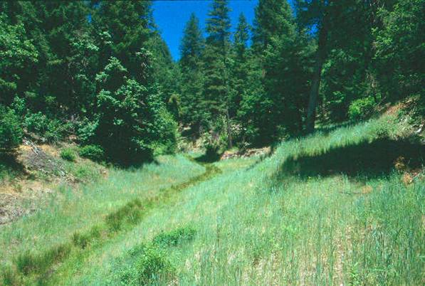
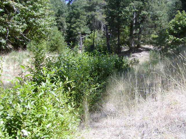
TRMs enhance the natural ability of vegetation to protect soil from erosion. The flexible 3-dimensional structure retains seeds and soil, and synergistically meshes with developing plant roots and shoots (ECTC, 1997; USEPA, 1999). Vegetated TRMs have resisted flow rates in excess of 4.3 m/sec (14 ft/sec) for durations of up to two days, providing twice the erosion protection of unreinforced vegetation (Austin and Theisen, 1994). Thus, TRMs can greatly increase the maximum permissible velocity for earthen drainage channel boundaries
6. PLANNING
Useful for Erosion Processes:
Toe erosion with upper bank failure Scour of middle and upper banks by currents
Local scour Erosion of local lenses or layers of noncohesive sediment
Erosion by overbank runoff General bed degradation
Headcutting
Piping
Erosion by navigation waves
Erosion by wind waves
Erosion by ice and debris gouging General bank instability or susceptibility to mass slope failure
Spatial Application:
Instream Toe Midbank Top of Bank
Hydrologic / Geomorphic Setting
Resistive Redirective Continuous Discontinuous Outer Bend Inner Bend Incision Lateral Migration Aggradation Conditions Where Practice Applies:
TRMs are designed to provide protection to resist channel and streambank erosion, and are useful when underlying soil boundaries may subside or shift slightly after installation.Complexity:
Moderate. This technique is relatively simple and straightforward to implement. Turf Reinforcement Mats are pre-manufactured and supplied in rolls that are simply unrolled and staked in place with pins and staples following in a pattern dictated by the slope gradient and type of soil. Mat manufacturers usually provide recommended attachment patterns and procedures.Design Guidelines / Typical Drawings:
There are three types of TRMs, and their application depends on the site condition, as shown in Table 1.TABLE 1: Recommendations for TRM applications (ECTC, 2001)
Minimum tensile
strength retained after 1000 hr.
(ASTM D 4355)
(%)Tensile Strength1,2
(ECTC 4 mod. ASTM D5035)kN/m (lb/ft)
(ASTM D6460 or other ECTC approved tests)
Pa (lb/ft2)1 Minimum average roll values, machine direction.
2 Field conditions with high loading and/or high survivability requirement may warrant the use of TRMs with tensile strength of 44 kN/m (3000 lb/ft or greater)
3Max. shear stress TRM (fully vegetated) can sustain without physical damage or excess erosion during a 30-minute flow event. (Note: fully vegetated shear stress properties for TRMs containing degradable components must be obtained on the nondegradable portion of the matting alone.)
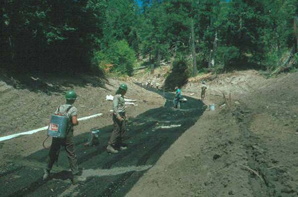
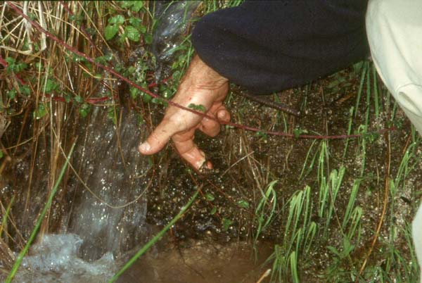
4 Erosion Control Technology Council – Technical Guidance Manual for Testing Rolled Erosion Control Products.TRMs can be installed after applying seed to the prepared soil surface or deployed first, and then seeded following infilling with soil. The former method allows the roots and shoots to grow through and interlock with the geosynthetic matrix, as shown in the second figure above. The channel or bank surface requires careful preparation, must be uniform and relatively free of rocks, stumps, clods etc, to ensure that there is complete contact between the TRM and the soil surface. General installation guidelines for TRMs used on slopes and channels has been published by the Erosion Control Technology Council (ECTC) (Lutyens, 1997). In addition, BioDraw provides detailed figures showing installation practices.
The number of anchoring stakes or staples per m (or ft) is site and product specific, and should be determined according to the manufacturer’s specifications. See Table 2 for stake sizing recommendations. Live willow stakes may be substituted for metal or wooden anchoring stakes, although it should be noted that willows could shade out turf grass. Willow wattles or fascines may be used to anchor the mats into the slots.
TABLE 2: Recommendations for TRM stake selection (Honnigford, 2003)
Typical soil conditions. Six-inch staples used in all but loose soil types. Loam, relatively loose sandy loam to sandy soils. Eight-inch staples are typically used in high velocity channel applications. Excessively loose soils, slopes containing fine silt, sand, or soft mud. Deep and soft fills, loose sands, silts, loams or "quick" conditions. Staples 12 inches and longer are used in shoreline applications in which wave action is a factor or in instances where soils remain saturated for long periods of time.
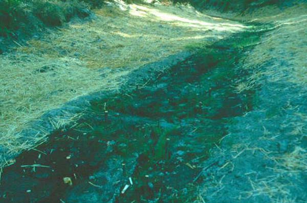
TRMs provide immediate cover and protection, and facilitate vegetation establishment
by moderating soil temperature, maintaining soil moisture, preventing desiccation,
and protecting seeds from seminivores. Even if herbaceous vegetation fails
to grow, the mats will provide protective cover for several years.
11. LIMITATIONS
Current testing indicates TRMs are of limited effectiveness when flow velocities
exceed 7.6 m/s (25 ft/s) or when sheer stresses are above 49 kg/m 2 (10 lb/ft
2) for a 30-minute flow duration in a vegetated condition (SI, 2003).
12. MATERIALS AND EQUIPMENT
TRMs may be installed either with hand labor or equipment; the main tools
or equipment required consist of hammers, stapling devices, and shovels or
equipment for trenching.
13. CONSTRUCTION / INSTALLATION
TRMs (in channels) typically require very special installation and
construction techniques. The following installation
specifications
were
derived from the ECTC Guidelines for Installing Rolled Erosion Control
Products (Honnigford, 2003).
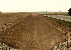
1. Site Preparation
The site should be fine graded to a smooth profile and relatively free from all weeds, clods, stones, roots, sticks, rivulets, gullies, crusting and caking. Fill any voids and make sure that the channel is compacted properly.2. SeedingSeed the area to be vegetated with a seed mix adapted to the local geographical area and soil conditions. Choosing the appropriate seed mix will ensure optimum germination, root system development, vegetation density, and long term functionality. The types of seeds planted above the anticipated water line may differ from those below the anticipated water line.
If the prepared seed bed becomes crusted or eroded, or if ruts or depressions exist for any reason, prior to RECP installation, the contractor should rework the soil until it is smooth and re-seed reworked areas.3. TRM installation in channel bottom.TRMs should always be unrolled in the direction of water flow.4. Check Slots
First, install the TRM in the channel bottom. Try to minimize the number of seams that are placed on the bottom of the channel, as these are sites of weakness. Do not put seams in the center of the channel bottom or in areas of concentrated water flow. When installing two TRMs side by side in a waterway, the center of the TRM should be centered in the area of concentrated water flow. Install adjoining TRMs away from the center of the channel bottom. Follow the manufacturer’s recommendations for overlapping the TRM; generally the overlap will be 50 to 100 mm (2 to 4 in).
Secure the TRM at the beginning of the channel with a 150 mm x 150 mm (6 in x 6 in) check slot dug perpendicular to the direction of water flow across the entire width of the channel. Lay the TRM in the check slot with 750 mm (30 in) extending upstream of the check slot. Stake or staple the TRM in the check slot on 300 mm (12 in) centers. Backfill the anchor trench and compact the soil. Place seed over the compacted soil if necessary. Cover the compacted soil with the remaining 300 mm (12 in) of the terminal end of the TRM. Staple or stake the terminal end of the TRM down slope of the anchor trench on 300 mm (12 in) centers.
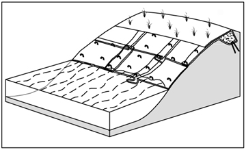
"Check slots" (cutoff trenches) must be provided every 7.5 to 15 m (25-50 ft) to ensure water moving under the TRM is forced back to the surface. Longitudinal check slots are required to ensure off site "side flows" do not get under the TRM. Similarly, beginning and terminal check slots are critical.5. Installation on Side Slopes
Check slots can be installed in one of two ways, depending upon the Engineer's discretion and/or the manufacturer’s recommendations.
One type of check slot is constructed by installing a double row of staples or stakes staggered and spaced 100 mm (4 in) apart.
The second option is to install a check slot 150 mm (6 in) wide by 150 mm (6 in) deep, and secure the TRM in the upstream side of the check slot with staples or stakes on 300 mm (12 in) centers. Then flip the TRM roll on the upstream edge. Back fill the check slot and compact the soil. Continue rolling the TRM downstream over the completed check slot.As the TRM is installed from the channel bottom up the slope, a shingle-type installation is recommended with the up-slope TRM overlapping the lower TRM approximately 50 to 100 mm (2 to 4 in).6. Terminal End
Anchor the TRMs with a minimum of one staple every 60 mm (24 in) across the width and one staple every 90 mm (36 in) down the length.
If the TRM needs to be spliced, "shingle" it as discussed above, with a 100 mm (4 in) overlap. Use a staple check slot to secure the overlap.
Anchor the RECP placed at the top of the channel slope in the same manner as described in the slope section.
Secure the TRM at the terminal end of the channel with a check slot similar to the one made at the beginning of the channel.Alternative Channel Installation Method
Another installation method for TRMs is to install them vertically and approximately 1 m (3 ft) onto the flat of the channel bottom. Construct a check slot in areas of concentrated water flow. Use a 50 to 100 mm (2 to 4 in) shingle-type overlap upstream to downstream.
a) The type of TRM material required,
b) Site conditions, such as the underlying soils, the steepness of the slope, and other grading requirements,
c) Installation-specific factors such as local construction cost (USEPA, 1999).
15. MAINTENANCE / MONITORING
Basic monitoring consists of periodic visual inspections to determine mat
integrity and attachment performance. Rill development beneath the mat or edge
lifting are evidence of inadequate attachment. Additional staking and trenching
can be employed to correct defects. Recently placed mats may be replaced, but
once vegetation becomes established, replacement is not a reasonable option.
16. COMMON REASONS / CIRCUMSTANCES FOR FAILURE
Critical points in conveyance system applications where mats can lose
support include points of overlap between mats, projected water surface
boundaries and channel bottoms.
17. CASE STUDIES AND EXAMPLES
|
|
|
|
|
|
|
|
|
Please visit the Photo Gallery for more pictures.
18. RESEARCH OPPORTUNITIES
None identified.
19. REFERENCES
Austin, D.N. and Theisen, M.S. (1994), “BMW Extends Vegetation
Performance Limits”, GFR, Vol. 12, No. 4, IFAI, pp. 8-16.
Erosion Control Technology Council (ECTC). 1997. Erosion Control Technology
Council Guidance Manual.
Erosion Control Technology Council (ECTC). 2001. Recommendations on
Proposed FHWA FP03 Specification.
Honnigford, L. (2003). Stabilize Soil and Increase Profits - Guidelines for
Installing Rolled Erosion Control Products. Erosion Control Technology Council
publication. http://www.ectc.org/resources/article_installing_recp.html
Lutyens, D. 1997. The ECTC’s Installation Guidelines for Rolled
Erosion-Control Products. Geotechnical Fabrics Report, Vol. 15, No. 6,
pp. 28-32. (pdf)
Synthetic Industries (SI) (2003). Landlock Turf Reinforcement Mats Innovative
Technology Inventory Entry. http://www.epa.gov/region1/assistance/ceit_iti/tech_cos/syntheti.html
(retrieved January 2004)
U.S. Environmental Protection Agency (USEPA). 1999. Storm Water
Technology Fact Sheet, Turf Reinforcement Mats. EPA 832-F-99-002.(pdf)