| LONGITUDINAL
STONE TOE |
|
1. CATEGORY
1.0 – River Training
2. DESIGN STATUS
Level I
3. ALSO KNOWN AS
Longitudinal Peaked Stone Toe Protection (LPSTP), stone toe, rock toe, stone
toe buttress, weighted riprap toe,
Longitudinal Fill Stone Toe Protection (LFSTP).
4. DESCRIPTION
Longitudinal stone toe has proven cost-effective in protecting lower banks
and creating conditions leading to stabilization and revegetation of steep,
caving banks (Figure 1 and Shields et al. 1995).
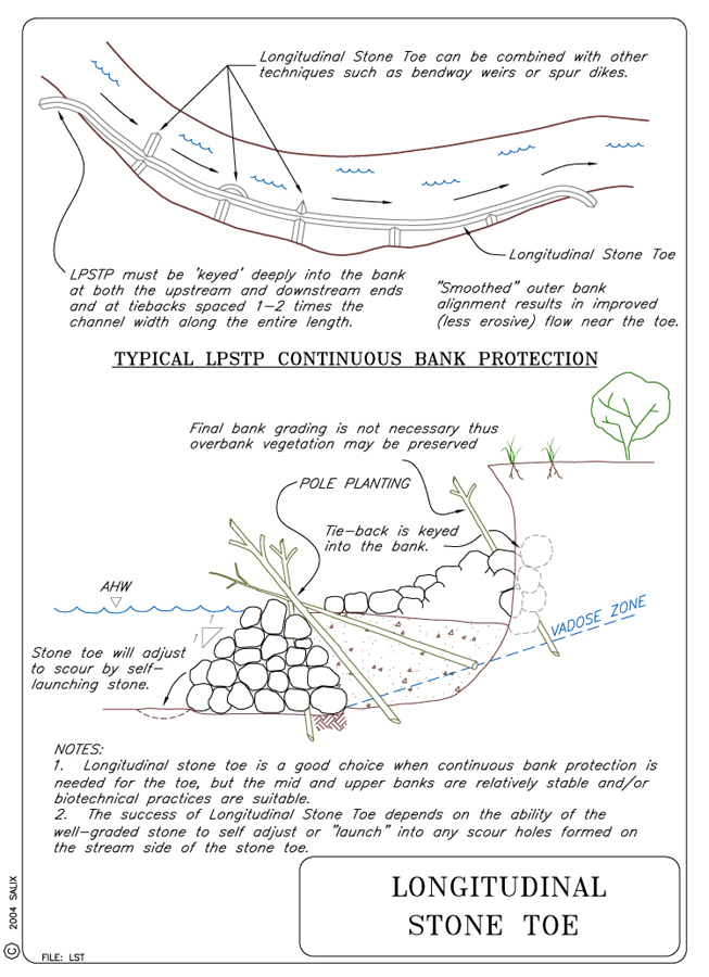
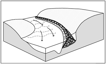
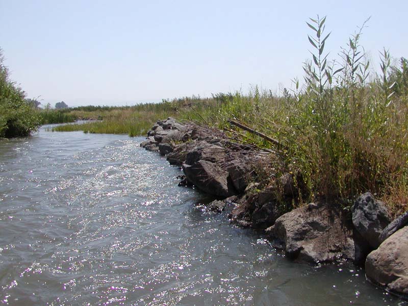
Stone toe is continuous bank protection consisting of a stone dike placed longitudinally
at, or slightly streamward of, the toe of an eroding bank (Figure 2). The cross
section of the stone toe is triangular in shape. The success of this method
depends upon the ability of stone to self-adjust or "launch" into
any scour holes formed on the stream side of the revetment. The stone toe does
not need to follow the bank toe exactly, but should be designed and placed
to form an improved or "smoothed" alignment through the stream bend
(Figure 2). The "smoothed" longitudinal
alignment results in improved flow (less turbulence) near the toe of the eroding
bank.
 |
 |
|
|
5. PURPOSE
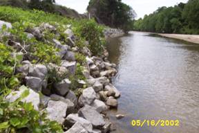
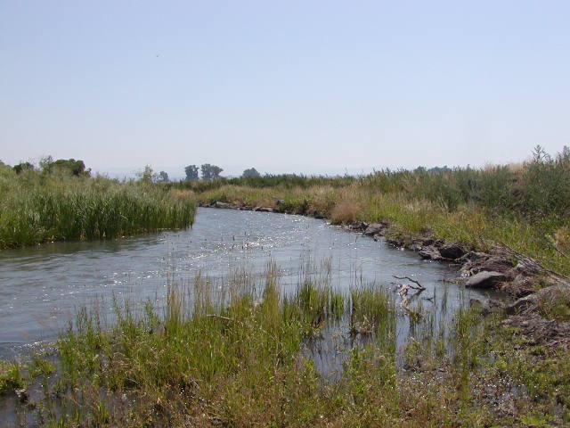
This continuous bank protection technique protects the toe from erosion. It is especially effective in streams where most erosion is due to relatively small but frequent events. It protects the toe so that slope failure of a steep bank landward of the stone toe will produce a stable angle. Such a bank is often rapidly colonized by natural vegetation (Figure 3).
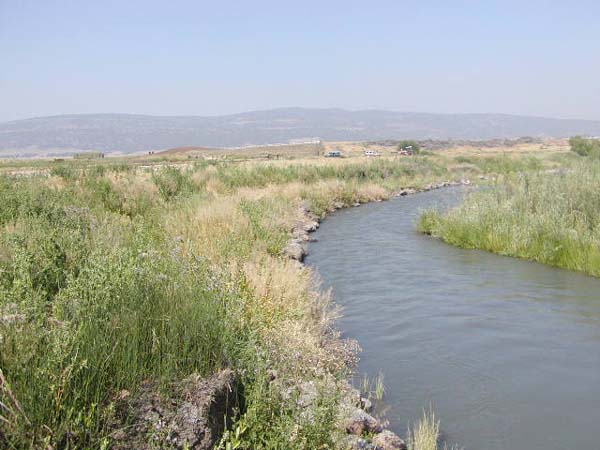
Figure 3. Revegetation of eroding bank landward of stone toe.
Photo by J. McCullah
6. PLANNING
Useful for Erosion Processes:
Toe erosion with upper bank failure Scour of middle and upper banks by currents Local scour Erosion of local lenses or layers of noncohesive sediment Erosion by overbank runoff General bed degradation Headcutting Piping Erosion by navigation waves Erosion by wind waves Erosion by ice and debris gouging General bank instability or susceptibility to mass slope failure
Spatial Application:
Instream Toe Midbank Top of Bank
Hydrologic / Geomorphic Setting
Resistive Redirective Continuous Discontinuous Outer Bend Inner Bend Incision Lateral Migration Aggradation Conditions Where Practice Applies:
Longitudinal stone toes are well-suited for many situations where relatively low-cost, continuous bank protection is needed, and is particularly applicable for ephemeral, narrow, and small- to medium-sized streams. Stone toe is also well suited for areas where the toe is experiencing erosion but the mid and upper banks are fairly stable due to vegetation, cohesive soils, infrequent short-duration inundation, or relatively slow velocities.
In addition, stone toe is well-suited for banks experiencing general slope instability. The toe is placed far enough from the top bank so that failure of the bank produces a stable angle. The stone provides additional loading and armoring of the toe to ensure that the newly formed bank is not undermined. Establishment of vegetation on the new bank just landward of the stone toe is essential for long term success.
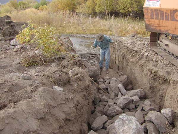
Figure 4. Construction of keys provides an opportunity for deep planting willow poles.
Longitudinal stone toe can be applied in some situations where the bankline needs to be built back out into the stream, where the existing stream channel needs to be realigned, where the outer bank alignment makes abrupt changes (scallops, coves, or elbows), or where the stream is not otherwise smoothly aligned.
Complexity:
Low.
Design Specifications / Typical Drawings:
Longitudinal stone toe can be specified by weight per unit length or to a specific crest elevation. A specific crest elevation may be specified when the bed of the stream is uneven or deep scour holes are evident. Maynord (1994) presents a design procedure for "launchable riprap" that may apply to stone toe in situations where scour on the water side of the toe is likely. Maynord (1994) categorizes launchable riprap as windrow, longitudinal fill, or weighted riprap toe. Longitudinal fill stone toe or weighted riprap toe are similar to stone toe except that the cross section may be rectangular rather than triangular or peaked. The dimensions for the weighted riprap toe are based on projected scour depth and a minimum "thickness", which corresponds to stone toe height of 2.5 to 4 times the maximum stone diameterabout 1 to 1.5 m (3 to 5 ft).
Longitudinal stone toe side slopes should be equal to the angle of repose. Typically stone toe applied at a rate of 3 metric tons of stone per lineal m (1 T/ft) of protected bank will have a height of approximately 1 m (3 ft). Stone toe constructed with 6 metric tons per m (2 T/ft) stands approximately 1.5 m (5 ft) tall, whereas 1.5 metric tons/m (0.5 T/ft) is approximately 0.6 m (2 ft) tall.
Longitudinal stone toe must be keyed deeply into the bank at both the upstream and downstream ends and at regular intervals along its entire length. On small streams, 25- 30 m (75-100 ft) spacing between keys (tie-backs) is typical, while on larger streams and smaller rivers, one or two multiples of the channel width can be used as a spacing guide. Excavation of trenches for keys provides a good opportunity for deep planting willow (Salix spp) posts or poles (Figure 4). The toe itself does not need to be keyed into the streambed because of its ability to "self-launch". However, in areas where the bed of the stream is uneven or deep scour holes are evident, the crest of the structure should be constructed to a specific elevation.
The key trenches at the upstream and downstream ends should be excavated into the bank at an angle of approximately 30°, with the primary flow direction and of sufficient length that flows will not be able to get around them during the design storm. A gentle angle is important for the end keyways, often referred to as "refusals", because it allows for smooth flow transitions coming into and flowing out of the treated reach. Tiebacks or "refusals" oriented at 90° to the bank have resulted in many failures at the downstream end of the structure, due to flow expansion at that point (D. Derrick, personal communication, 2000).
Longitudinal stone toe has documented environmental benefits, especially for aquatic habitat. Stone interstices provide cover and habitat for smaller fish and other organisms, and rocky surfaces provide stable substrate for benthic invertebrates. Fish habitat provided by stone toe has been found generally inferior to that provided by intermittent, redirective measures like Spur Dikes, Vanes, or Bendway Weirs (Shields et al., 2000; Knight and Cooper, 1991). Vegetative cover can become established, even growing through the rock, and can provide canopy and a source of woody debris. Bank grading, reshaping, or sloping is usually not needed (existing bank and overbank vegetation need not be disturbed or cleared), nor is a filter cloth or gravel filter needed. If stone is placed from the water side, existing bank vegetation need not be disturbed.
8. HYDRAULIC LOADINGPermissible shear and velocity for longitudinal stone toe is related to the size of rock used in construction. Other factors, such as the angularity of the stone, the thickness of the layers of stone, and the angle at which the faces of the stone structure are constructed also come into play. See comments regarding stone sizing in the section below on materials and equipment.
9. COMBINATION OPPORTUNITIESA variety of techniques can be used with Longitudinal Stone Toe. Willow posts and poles may be incorporated into key sections (Figure 3) and used to revegetate the middle and upper bank above stone toe. Aquatic habitat benefits may be increased by incorporating Spur Dikes, Vanes, Bendway Weirs, Large Woody Debris Structures, or Stone Weirs into the protection scheme. Live Siltation, Live Brushlayering, Live Brush Mattresses, Live Staking, Live Fascines, Turf Reinforcement Mats, Erosion Control Blankets, Geocellular Containment Systems, Vegetated Articulated Concrete Blocks, Vegetated Riprap, Soil and Grass Covered Riprap, and Vegetated Gabion Mattress may all be used to provide rapid revegetation and additional protection on middle and upper banks. Cobble or Gravel Armor, Vanes with J Hooks, Cross Vanes, Boulder Clusters, and Newbury Rock Riffles may be used to enhance benthic and water column habitats. Longitudinal Stone Toe with Spurs is a variation on this technique.
10. ADVANTAGES
Bank grading, reshaping, or sloping is usually not needed (existing bank
and overbank vegetation need not be disturbed or cleared), and a filter
cloth or gravel filter is not needed. Longitudinal stone toe is very cost-effective
and is relatively easy to construct. It is simple to design and specify
and is a thoroughly tested method that has been used in a variety of situations
and has been extensively monitored. Another advantage is that it is easily
combined with other bank stability techniques that provide superior habitat
compared to pure riprap.
11. LIMITATIONS
Longitudinal stone toe only provides toe protection and does not protect
mid- and upper bank areas. Some erosion of these areas should be anticipated
during long-duration, high energy flows, or until the areas become otherwise
protected (biotechnical techniques). Stone toe is not suitable for reaches
where rapid bed degradation (lowering) is likely, or where scour depths
adjacent to the toe will be greater than the height of the toe.
12. MATERIALS AND EQUIPMENT
Stone for the structure should be well graded and properly sized.
Detailed guidance for sizing stone for bed and bank stabilization
structures is beyond the scope of this guideline, and many approaches are
available (see Special Topic: Designing
Stone Structures). However, the Maynord (1995) equation gives
a D50 stone size for an angular stone riprap revetment of 0.875
m (2.9 ft) if the near-bank vertically averaged velocity is 3.5 m/s (11.5
ft/s), and flow depth = 1 m (3.3 ft), and stone is placed on a bank slope
of 1V:1.5H. Use of riprap larger than this is unusual.
13. CONSTRUCTION / INSTALLATION
All longitudinal stone toe should be constructed in an upstream to downstream sequence. This technique usually requires heavy equipment for excavation of the keys (tie-backs) and efficient hauling and placement of stone. Longitudinal stone toe can be constructed from within the stream, from roadways constructed along the lower section of the streambank itself, or from the top. The preferred method is from the point bar side of the stream (especially possible with ephemeral or intermittent streams), as this causes the least disturbance of existing bank vegetation. The least preferred is from the top of the bank, as it disturbs or destroys more bank vegetation and the machine operator's vision is limited.
Usually, the keyways are excavated first and rock is dumped into the key.
The rock is then formed into tie-backs (if needed) and finally the stone
toe is constructed along a "smoothed" alignment, preferably with
a uniform radius of curvature throughout the bend. In a multi-radius bend,
smooth transitions between dissimilar radii are preferred.
A reasonable relative cost to riprap for longitudinal stone toe is 0.3. Costs are dependent on cost of stone, hauling, and amount of stone used. Including stone for keys and tie-backs, typically 110 to 130 metric tons (120 to 140 tons) of stone will be used for each 30 m (100 ft) of protected bank when toe is placed at a rate of 3 metric tons per lineal m (1 ton/ft) of protected bank. Based on typical unit costs for stone (including delivery and placement), cost for this type of toe ranges from $50 to $115 per m (16 to $35 per ft) of protected bank.
15. MAINTENANCE / MONITORING
Stone toe structures rarely require maintenance. Maintenance and monitoring
requirements should be linked to consequences of failure.
16. COMMON REASONS / CIRCUMSTANCES FOR FAILURE
Features that should be monitored are similar to those for all stone structures:
loss of stone due to subsidence, leaching of underlying sediments, raveling
or excessive launching. Extreme scour or bed lowering on the stream side of
the toe can cause the entire mass of stone to launch, creating an opening or
gap in the longitudinal structure. If this situation is anticipated or encountered,
the problem can be remedied by adding more rock for additional width. See longitudinal
fill stone toe
Longitudinal stone toe may be flanked during extremely high flows if the key trenches are incorrectly built or if the tiebacks are spaced too widely or are constructed with inadequate amounts of stone. Terminal keyways or "refusals" oriented at 90° to the bank have resulted in many failures at the downstream end of the structure, due to flow expansion at that point (Derrick, Personal Communication, 2000). These terminal key trenches at the upstream and downstream ends should be excavated into the bank at an angle of approximately 30° with the primary flow direction and of sufficient length that flows will not be able to get around them during the design storm.
17. CASE STUDIES AND EXAMPLES
Several case studies and examples are provided by U. S. Army Corps
of Engineers (1981). Shields et al. (2000)
compared fish habitat and fish populations adjacent to stone toe,
bendway weirs, and willow posts along the same stream reach over
a three-year period.
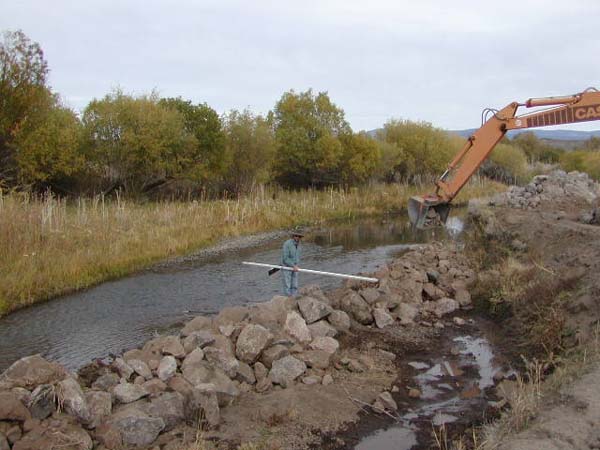
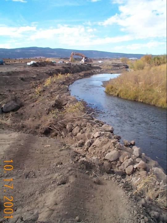
Flournoy Ranch, Pit River, Modoc County, California
Several hundred meters of longitudinal stone toe was utilized on this project which involved removal of decadent levees and meander restoration. See Hoyer et al., 2002.
 |
|
|
|
 |
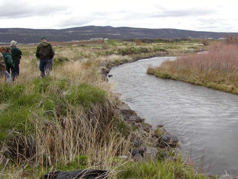 |
Looking upstream. |
Looking DS Same
reach 5/03 |
|
|
Velocities during this spring freshet were estimated at 3 m/s. This photo clearly depicts the bankfull or AHW elevation below which vegetation should not be relied upon. |
|
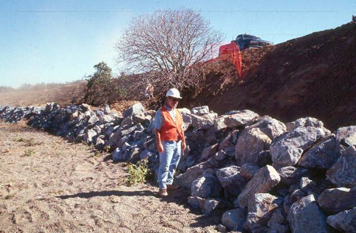
Dunnigan Burn Dump, Buckeye Creek, Yolo County, CA
Buckeye Creek is an ephemeral stream in Northern California that abuts a closed disposal site, the Dunnigan Burn Dump. Due to high flows in Buckeye Creek and extreme erosion from winter storms, burn ash and solid waste were being exposed along approximately 500 feet of the creek and carried downstream during periods of high water. Bendway Weirs were utilized in this remediation project to deflect the high-energy streamflows away from the exposed streambanks. For more information see McCullah and Hanford (1999). For complete documentation of the project, see the Construction Completion Report available from the Integrated Waste Management Board, 1001 I Street, P.O. Box 4025, Sacramento, CA 95812-4025 (916) 341-6000.
 |
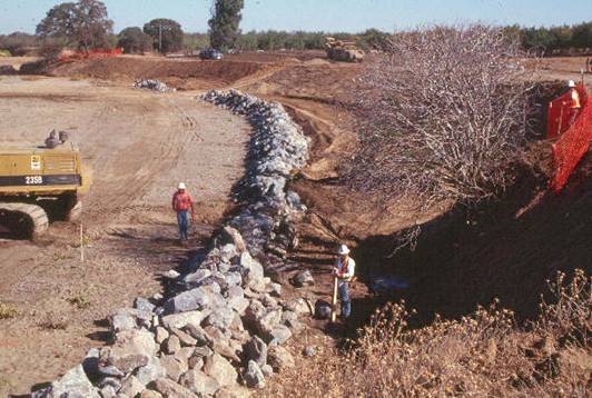 |
Longitudinal
Stone Toe being installed in Dunnigan, CA |
|
Please visit the Photo Gallery for more pictures.
18. RESEARCH OPPORTUNITIES
More quantitative design criteria are needed for tieback spacing and
angles for keyways (refusals).
19. REFERENCES
Hoyer, D., Harvey, C. & McCullah, J (2003) Restoration in the Pit River Watershed. Proceedings, International Erosion Control Association Conference, Las Vegas 2003. (pdf)
Knight, S. S., & Cooper, C. M. (1991). Effects of bank protection on stream fishes. In Proceedings of the Fifth Federal Interagency Sedimentation Conference, Federal Energy Regulatory Commission, Washington, D. C., 13-34--13-39.
Maynord, S. T. (1994). Toe scour protection methods. In: Hydraulic Engineering '94, G. V. Controneo and R. R. Rumer (eds.) American Society of Civil Engineers, New York, New York 1025-1029.
Maynord, S. T. (1995). Corps riprap design guidance for channel protection. In C. R. Thorne, S. R. Abt, F. B. J. Barends, S. T. Maynord, and K. W. Pilarczyk. (eds.). River, coastal and shoreline protection: erosion control using riprap and armourstone. John Wiley & Sons, Ltd., Chichester, U. K., 41-42.
McCullah, J. A., & Hanford, D. (1999) Bendway Weirs and Soil Bioengineering for California Burn Dump Remediation. Salix Applied Earthcare Publication. (pdf)
Shields, F. D., Jr., Bowie, A. J., & Cooper, C. M. (1995). Control of streambank erosion due to bed degradation with vegetation and structure. Water Resources Bulletin 31(3):475-489. (pdf)
Shields, F. D., Jr., Knight, S. S., & Cooper, C. M. (2000). Warmwater stream bank protection and fish habitat: a comparative study. Environmental Management 26(3):317-328. (pdf)
USACE. (1981). Final Report to Congress, The Streambank Erosion Control Evaluation and Demonstration Act of 1974, Section 32, Public Law 93-251. Main Report and Summary and Conclusions. Washington, D. C.