| CROSS VANES |
|
1. CATEGORY
3.0 – Riparian Buffer and Stream Corridor Opportunities
2. DESIGN STATUS
Level I
3. ALSO KNOWN AS
Vortex Weirs, Upstream-Pointing Chevrons
4. DESCRIPTION
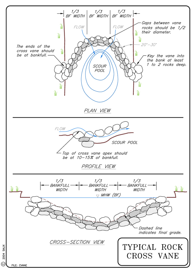
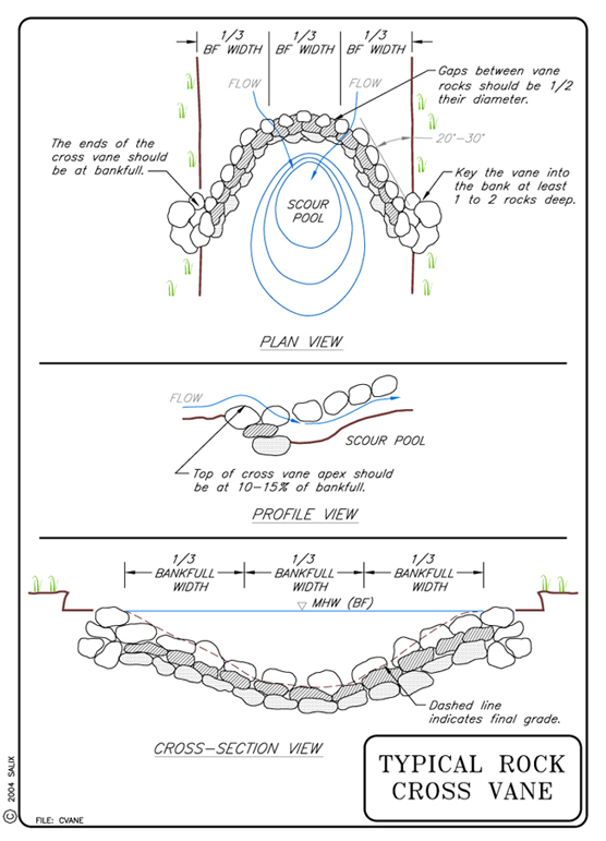
Cross vanes are "V" shaped rock structures stretching across the width of the stream, with the lowest part of the structure being at the vortex of the "V" located at the point farthest upstream. The downstream ends (the arms) of the "V" are keyed into the streambanks at bankfull elevation. This upstream-pointed shape forms a scour pool inside of the "V". Cross vanes are basically two vanes constructed on opposing banks. (see Technique: Vanes)
5. PURPOSE
Cross vanes are used to provide grade control, frequently providing enhanced aquatic and fisheries habitat. The vortex can be designed as a stable channel invert. Cross vanes are secondarily a redirective technique, functioning similar to Vanes and Vanes with J-hooks. Cross vanes redirect water away from the streambanks, and into the center of the channel. This serves to decrease shear stress on unstable banks, as well as creating aquatic habitat in the scour pools formed by the redirected flow. This allows flow approach angles to be controlled. By increasing shear stress in the center of the channel, cross vanes create a stable width/depth ratio, maintain channel capacity, and sustain sediment transport capacity and competence (Rosgen, 2001). By virtue of the ability to raise or maintain channel inverts, cross vanes can also be used to increase year-round flow to irrigation diversions. They are also useful to direct flows through the center of bridge abutments (Johnson, et al., 2002).
6. PLANNING
Useful for Erosion Processes:
Toe erosion with upper bank failure Scour of middle and upper banks by currents Local scour Erosion of local lenses or layers of noncohesive sediment Erosion by overbank runoff General bed degradation Headcutting Piping Erosion by navigation waves Erosion by wind waves Erosion by ice and debris gouging General bank instability or susceptibility to mass slope failure
Spatial Application:
Instream Toe Midbank Top of Bank
Hydrologic / Geomorphic Setting
Resistive Redirective Continuous Discontinuous Outer Bend Inner Bend Incision Lateral Migration Aggradation Boulder bed Cobble Bed Gravel Bed Sand bed Silt or clay bed Channel width < 15 m (49.2 ft) Channel bed slope between 0.005 and 0.2 (0.5% and 20%) Conditions Where Practice Applies:
Cross Vanes are used to decrease bank degradation in moderate to high gradient streams (Genesee / Finger Lakes RPC, 2001). This technique should not be used in bedrock streams, or those with a highly unstable substrate. It should also be avoided in streams with well-developed pool-riffle systems (Maryland, 2000; Genesee / Finger Lakes RPC, 2001). With proper analysis of geomorphic and sediment-transport conditions, cross vanes can provide a means to develop pool-riffle sequences. Cross vanes may be used to direct water for irrigation diversions.
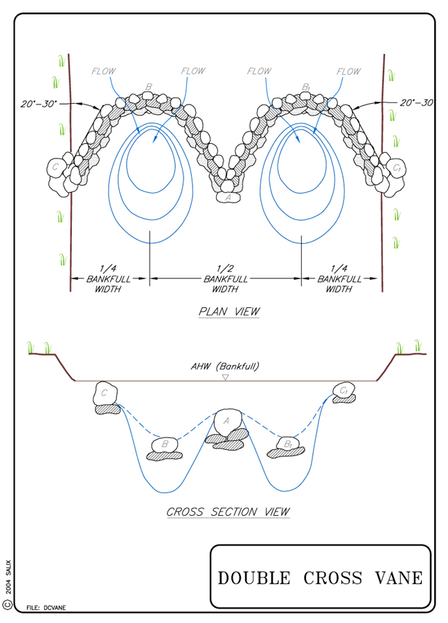
Double cross vanes or w-weirs serve the same purpose as single cross vanes, but are designed for stream and river widths of 12 m (40 ft) or greater. These structures create greater diversity of velocities and habitat opportunities across the channel, while developing a natural look in wide streams and rivers (Rosgen, 1996).
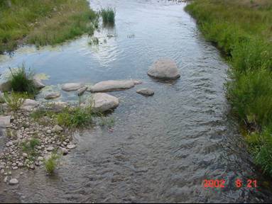
Double cross vane under low flows in Putah Creek, Yolo County, CA. Photo courtesy of Rich Marovich, Lower Putah Creek Coordinating Committee (LPCCC)
Double cross vane under higher flows in Putah Creek, Yolo County, CA . Note the direction of the flow and the still water against the bank and upstream from the arm of the vane. Photo courtesy of Rich Marovich, LPCCC
Complexity:
Moderate.
Design Guidelines / Typical Drawings:
Hydraulic Considerations: The primary design consideration for Cross Vanes is the elevation of bankfull stage (see Special Topic: Bankfull Discharge). The center 1/3 of a Cross Vane carries 80% of the bankfull discharge, while the arms only transport 10% each; therefore, it is imperative that the apex of the arc be securely constructed and appropriately keyed in. Cross vanes are independent of design high-water and freeboard because vegetation establishment is the most common bank protection from bankfull stage to top of bank.
Height: Similar to standard vanes, the height of the cross vane arms at the bank should reach, but not exceed, the bankfull or AHW stage elevation (see Special Topic: Bankfull Discharge). The cross vanes must be keyed into the bank at least 3 m (10 ft). If the bank is higher than bankfull, Rosgen suggests building a bench at bankfull elevation to key in the weir. David Derrick (personal communication, 2002) and Biedenharn et al., (1997), recommend overfilling the keyway to counteract settling and subsequent overland flow erosion of the key. Additional stability and erosion control can be gained by planting the keyway excavations with Willow Poles or Live Siltation prior to backfilling. (See Typical Vane Key Detail, Willow Posts and Poles, Live Siltation, and the Special Topic: The Key to Stability is the Key)
Crest Slope: Vanes are designed to be overtopped at the tip by all but the lowest flows and should pitch from the bank to the tip of the vane with a 3 to 7% slope. Steeper vanes act more like spurs or barbs and have different effects on scour and velocity ( Maryland, 2000; Johnson et al., 2001; and Rosgen, 2001).
Grade Control Spacing: Rosgen (2001) provides the following equation for calculating appropriate pool spacing when using Cross Vanes as grade control structures.
(Space between pools)/Bankfull width = 8.2513 (Channel slope (%)) -0.9799
This empirical relation gives a pool spacing consistent with classical stream geomorphology, (average pool spacing ~ 5-7 times channel width) if slope is between 1.2% and 1.6%, but gives unrealistic values for slopes greater than 2% or less than 1%. An additional factor to consider when spacing vanes is the crest elevation of each vane; vanes should be spaced far enough apart that the backwater from the downstream vane does not submerge the riffle of the upstream vane, and thus produce a sequence of rather uniform pools with no riffles or runs. Pool spacing should not be constant, but should vary about a realistic mean value.
Rock Gradation and Shape: When possible, vanes should be constructed with graded (self-launching) stone. Self launching rock can be placed on the existing substrate however footer rocks are recommended for the vortex of the cross vane. The Corps of Engineers has stone gradations for Class A, Class B, and Class C rock (see Special Topic: Self Launching Stone). The Kansas State Conservation Commission has been building vanes and bendway weirs from "shot rock" which generally has a high percent of fines. In very sandy-bottomed streams, it is advantageous to build vanes using "shot rock" or well-graded stone that includes fines, as they prevent ‘through-flow’ of sand, and subsequent scour (McCullah, 2004; P. Balch, personal communication, 2002).
Rocks for Vortex: Two types of rock are required: long, flat footer rocks, and angular vane rock. Footer rocks should be relatively long and flat (longest axis should be at least 3.5 times the shortest axis), while the vortex rocks should be both big enough to reach the desired height when buried in the streambed, and be sized to resist movement from shear stress expected from the design flow. Should these criteria conflict, the larger of the two sizes should be used. The depth of the trench for the footer rocks varies depending on bed material. For a gravel or cobble bed stream, a depth of twice the diameter of the average vane rock is recommended for the footer trench (Rosgen, 2001; Maryland, 2000). The footer rocks should be placed with a gap between the stones equal to 1/3 their diameter which allows them to interlock as the vane adjusts and equilibrates (Rosgen, 2001). In sandy bed material, or where excessive scour is predicted, the trench depth should be four times the diameter of the average vane rock and the gaps between the rocks should be eliminated. It may be feasible to place a filter fabric geotextile under the footer stones on sand-bed streams. See Rock Gradations above.
When to use footers: The footer rocks should be heavier, longer, and flatter than the average vane rocks. As a rule of thumb, the weight of the heaviest footer rock is comparable to the heaviest rock used for riprap for the design flow (Maryland, 2000; Harman & Smith, 2000). In sandy streams an extra layer of footer rocks may be necessary to compensate for the additional scour. Even in small sand bed streams, 2 m (6.6 ft) of scour next to a structure like this is not uncommon (D. Shields, personal communication, 2004). Empirical formulas are available for scour depth (Kuhnle et al. 1999 and 2002).
The size of the rock will depend upon the stream size and shear stress. See comments below under "Hydraulic Loading" on rock sizing. Some state DOTs (or state resource agencies) have published guidelines for specifying rock size, density and durability (Maryland, 2000).
General: The arms of the cross vane should be constructed at an angle of 20 to 30° away from the bank in the upstream direction (see Typical Drawing). The angles and lengths of the arms can be modified in order to direct the high-energy water in a specific direction. The slope of the arm (vane) crests should be between 2 and 7% from the top at the bank to the invert at the upstream end (Rosgen, 2001).
For double cross vanes, the angle of departure from the bank is normally the same as standard cross vanes. The crest of the vane rises from the bed elevation at points located at ¼ and ¾ of the channel width in the downstream direction to the center of the bankfull channel, which forms a "W" shape with two thalwegs developed at the structure (Rosgen, 2001).
7. ENVIRONMENTAL CONSIDERATIONS / BENEFITS
Cross Vanes may be used as habitat improvement structures. Rosgen presents a partial list of these factors:
Increase in bank cover due to an increase in water level at the bank above the weir.
Creation of holding pools and refuge cover in the scour pool during high and low flows.
Creation of "feeding lanes" for fish at the interface between fast and slow moving water. This is created where the high-energy flow in the center of the channel interacts with the calm water surrounding the scour pool.
In addition, cross vanes can contribute to bed stability.
8. HYDRAULIC LOADING
Allowable hydraulic loading is related to stone size. Other factors, such as the angularity of the stone, the thickness of the layers of stone, and the angle at which the faces of the stone structure are constructed also come into play.
Detailed guidance for sizing stone for bed and bank stabilization structures is beyond the scope of this guideline, and many approaches are available (see Special Topic: Designing Stone Structures). However, the Maynord (1995) equation gives a D50 stone size for an angular stone riprap revetment of 0.875 m (2.9 ft) if the near-bank vertically averaged velocity is 3.5 m/s (11.5 ft/s), and flow depth = 1 m (3.3 ft), and stone is placed on a bank slope of 1V:1.5H. Use of riprap larger than this is unusual. Considerable velocity and shear stress can be withstood if rocks are large enough. However, extremely large rock may be unavailable, and can be difficult to place with available equipment. Also, rock much larger than channel bed material will trigger local scour problems.
9. COMBINATION OPPORTUNITIES
Since cross vanes can successfully reduce near-bank velocities and shear stress, vegetation establishment is greatly improved. Vanes are often combined with other biotechnical soil stabilization measures for bank areas between the vanes. Vegetated ground cover techniques such as Turf Reinforcement Mats, Erosion Control Blankets, Live Stakes, Live Brush Mattress, and Vegetation Alone are appropriate candidates for combination. Cross vanes are sometimes used in conjunction with continuous and resistive armoring measures, such as Cobble or Gravel Armor, Vegetated Riprap or Longitudinal Stone Toe, when additional protection between the vanes is required. Live Brushlayering, Willow Poles, and Live Siltation are extremely effective when implemented at the bank during excavation of the keyways. Posts and Poles can be used create overhanging cover for pools up- or downstream from cross vanes (Shields et al., 1995).
10. ADVANTAGES
Rosgen (2001) lists the advantages of Cross Vanes as follows:
1. Maintains grade control.
2. Reduces erosion of streambanks.
3. Facilitates sediment transport.
4. Facilitates irrigation diversion gates.
5. Enhances aquatic habitat.
6. Maintains an appropriate width/depth ratio.
7. Enhances recreational boating.
8. Maintains river stability.
9. Dissipates excess energy.
10. Will withstand large floods.
11. Maintains channel capacity.
12. Compatible with natural channel designs,
13. Visually acceptable to the public.
11. LIMITATIONS
This technique should not be used in bedrock streams, or those with a highly unstable substrate. Cross vanes are not useful for controlling erosion in rapidly incising channels. It should also be avoided in streams with well developed pool-riffle systems (Maryland, 2000; Genesee / Finger Lakes RPC, 2001).
12. MATERIALS AND EQUIPMENT
In stream restoration projects, attempt to obtain rock that is as similar to the native rock as possible. Logs can also be used to construct the arms of the vanes; however, Rosgen (2001) suggests that geotextiles filter fabric be used to prevent scour under logs.
An excavator with a thumb will make rock placement easier.
13. CONSTRUCTION / INSTALLATION
Construction will require excavation of keys into both banks a minimum of 3 m (10 ft) to a height of bankfull elevation. If one or both of the banks are higher than bankfull, Rosgen suggests building a bench at bankfull elevation to key in the vane. The keyways should be constructed by digging a trench, placing rock and vegetation (as described in Willow Posts and Poles), "watering in" and then backfilling. If vegetative techniques are used, such as Willow Post and Poles or Live Siltation, the chances of successful establishment can be increased by "watering in" the cuttings.
In some cases, it may be necessary to divert or otherwise dewater channels during construction (Maryland, 2000; Genesee / Finger Lakes RPC, 2001).
Place footer rocks such that they lock together in the shape of the vortex and crest width. The footer rocks should be keyed in 3 times as far as they protrude above the streambed at the invert. In sandy-bottomed streams scour depth will be greater; therefore, footer rocks should be keyed in twice as deep, or 6 times as far as they protrude above the streambed.
Vortex (or Vane) rocks should be placed above the footer rocks. At the invert, the vortex rocks should be spaced about ½ their diameter apart, and gradually be placed closer together, so those contiguous to the bank touch one another (Maryland, 2000). The wide spacing at the invert will allow fish passage even at low flows. The elevation of the top of the rocks should progress from 10 to 15% of bankfull flow depth above the bed at the apex, to bankfull stage at the streambank (Maryland, 2000).
14. COST
Little actual cost data could be located, so a reasonable relative cost to riprap for Cross Vanes is estimated to be 0.5. It is assumed that under appropriate conditions, vanes can provide protection equivalent to rock riprap at approximately 1/2 the cost which is estimated at $148.00 per linear m ($46.25 per linear ft) of bank. Rosgen (2001) notes that a cross vane protects a minimum bank length of twice the vane arm length for each bank and this observation has been verified and demonstrated in several instances.
A series of log vanes were installed in Putah Creek, Yolo County, CA for $2,000 each. A 15 m (50 ft) wide double cross vane with a 1.2 m (4 ft) crest elevation was installed in Putah Creek, Yolo County, CA for $12,000 total.
15. MAINTENANCE / MONITORING
The cross vane should be inspected regularly. Maintenance staff should determine:
Is the vane intact?
Are flows being redirected where expected?
Is there any unintended scour?
Has the vane (or vane series) created or exacerbated erosion or lateral instability downstream of the structure?
16. COMMON REASONS / CIRCUMSTANCES FOR FAILURE
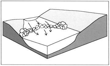
Most failures are related to undermining or flanking by scour (surface erosion) or seepage under and around the structure (subsurface erosion). Undermined structures may fall into the downstream scour hole. Structures built with undersized stone may unravel (stones from the crest are scoured and transported away). A cross vane that failed by flanking is shown in Figure 1.
Figure
1. Stone v-notch weir that failed by flanking. Photograph courtesy of Jon
Fripp.
17. CASE STUDIES AND EXAMPLES
Putah Creek, Yolo County, CA.
 |
 |
 |
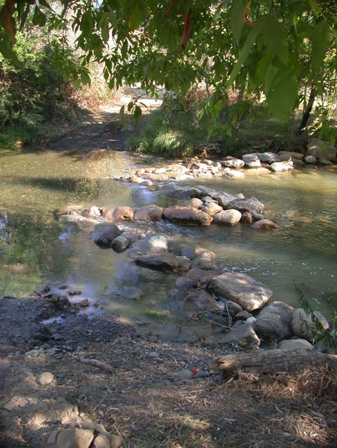 |
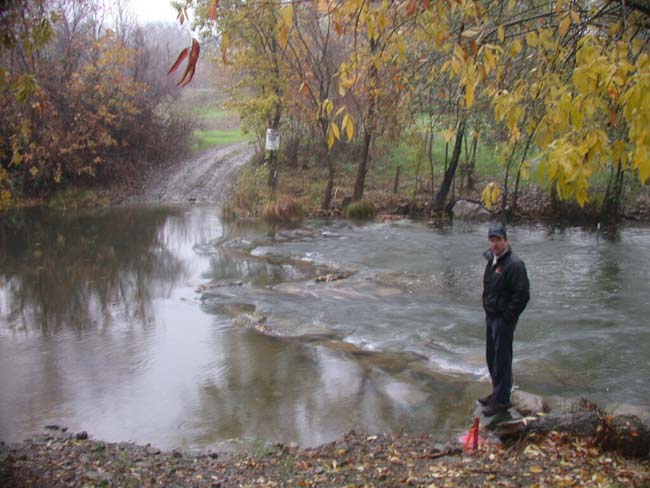 Putah Creek Double Cross Vanes approx 17 m3/s (600 cfs). |
 Putah Creek Double Cross Vanes approx .57 m3/s (20 cfs). |
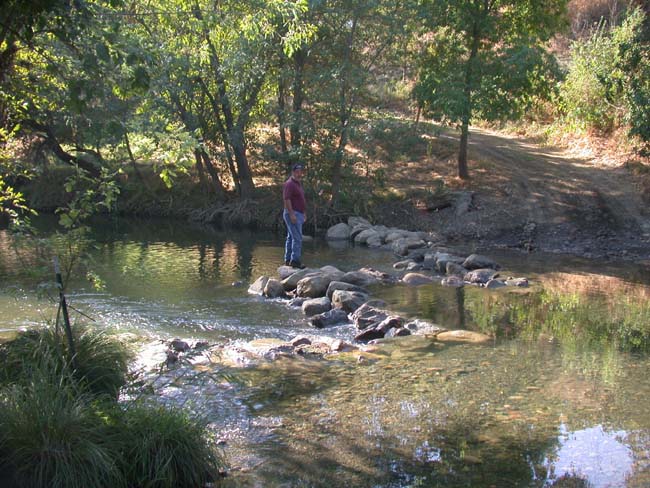
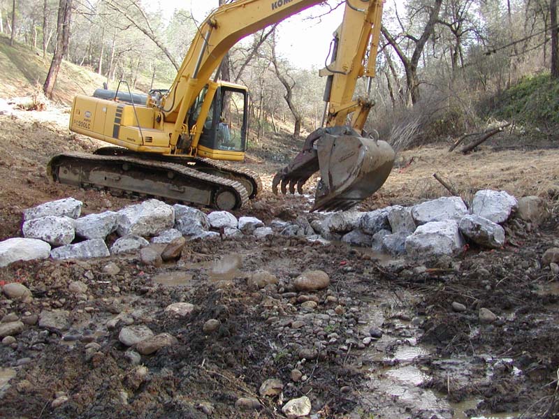
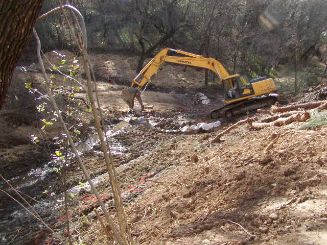
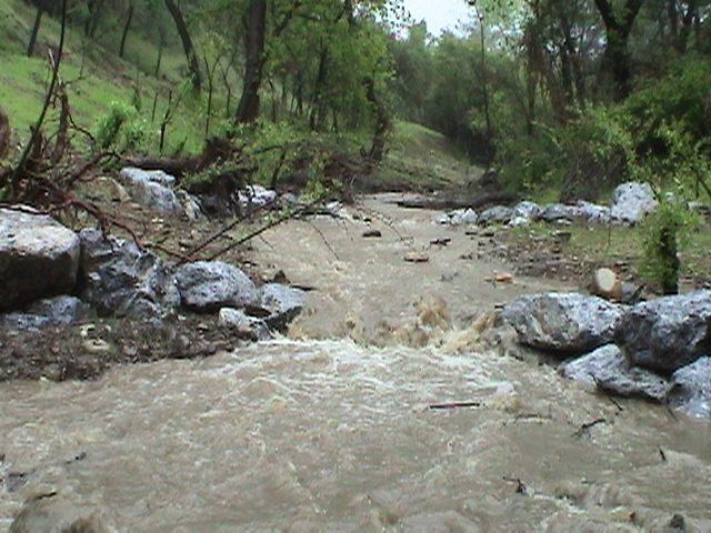
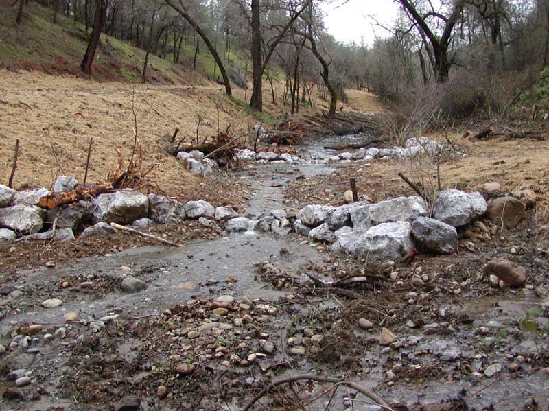
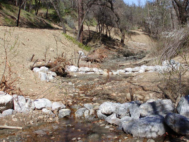
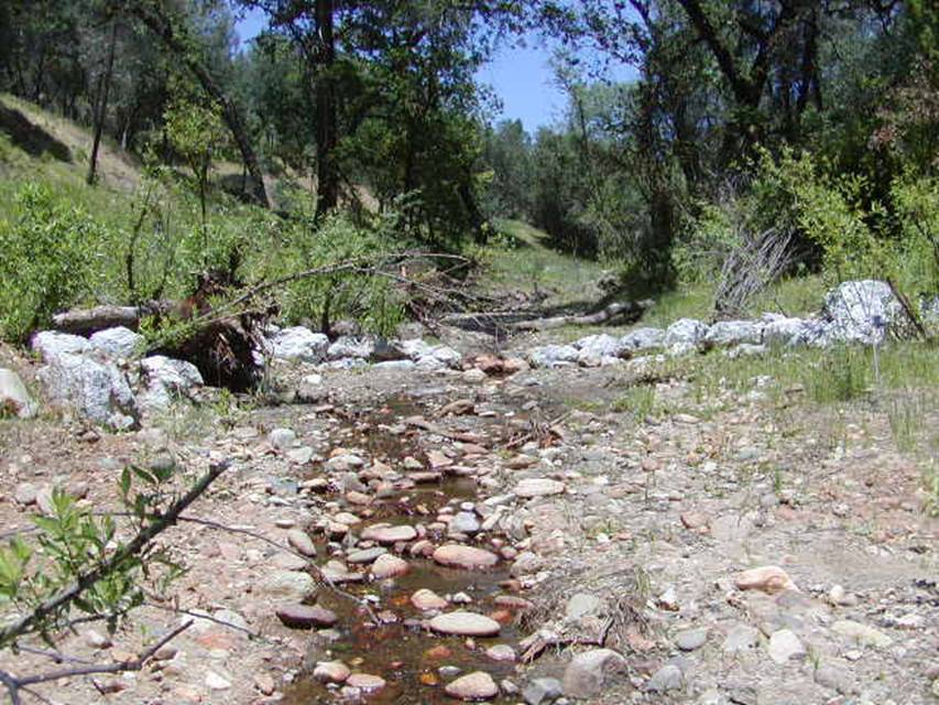
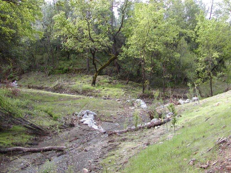
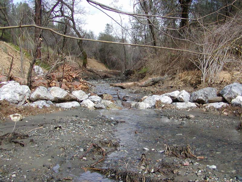
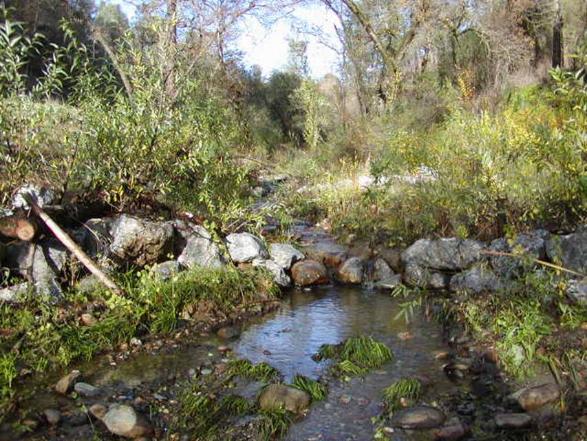
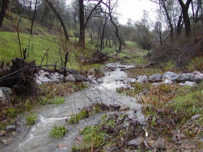
Old 99 Creek "Daylighting Project"
Two old homesites with failed culvert undercrossings had obstructed Old 99 Creek for over 80 years since the construction of Highway 99 and Shasta Dam near Redding, CA. The stream was small, with a 3 - 4 m (10 to 13 ft) bankfull width, but the failed culvert had resulted in the accumulation of over 5,000 m3 (6,539 yd3) of sediment in the creek and the subsequent loss of aquatic habitat and fish passage. This project removed the homesites, culvert, and sediment down to the historic creek bottom, and stabilized the restored channel with a series of two rock cross vanes and liberal willow post planting. The two cross vanes were designed to arrest downcutting while the stream adjusted to the new hydrologic conditions as a result of urbanization upstream. Secondarily, the cross vanes were used to protect the newly constructed banks by redirecting the flows to the center of the channel. Thirdly, the cross vanes produced instream habitat and scour pools.
The cross vanes took approximately 4 hours to build with a tracked excavator at an overall cost of $1000.00 each including Willow Post and Pole construction. The cross vanes protected an estimated 80 linear m (263 linear ft) of streambank. Both banks were protected for a distance of 40 linear m (131 ft) each of streambank. In Novemeber 2004, it was discovered that one of the Cross Vanes had failed due to a lack of footer rocks.
 |
 |
 |
 |
 |
 |
 |
 |
 |
 |
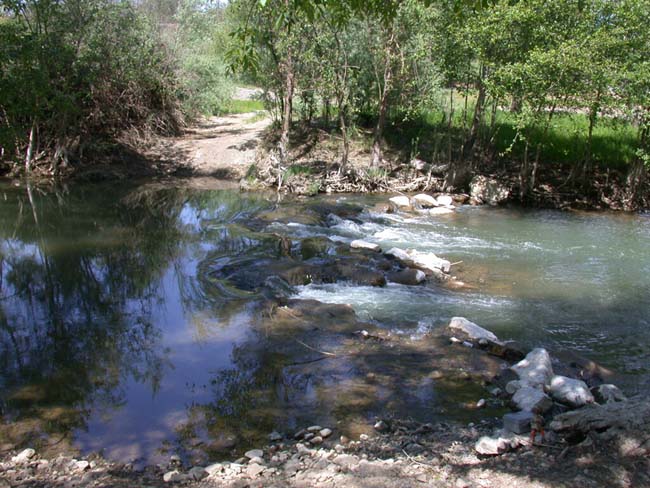
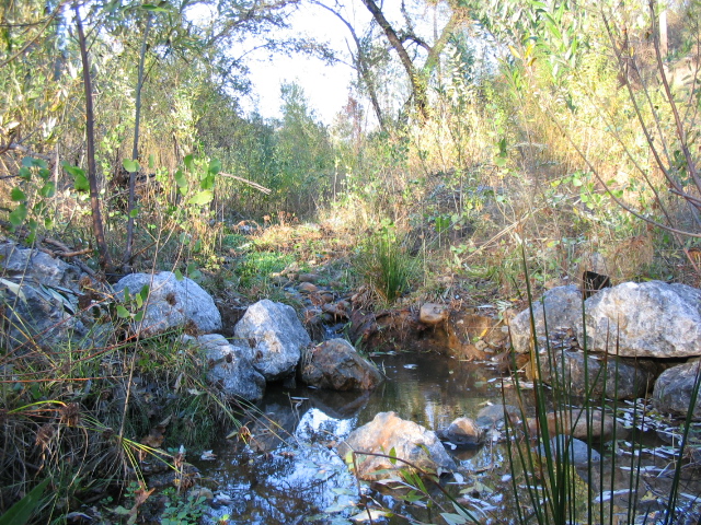
Cross
Vanes after installation. |
|
 |
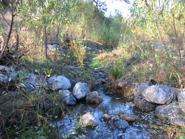 |
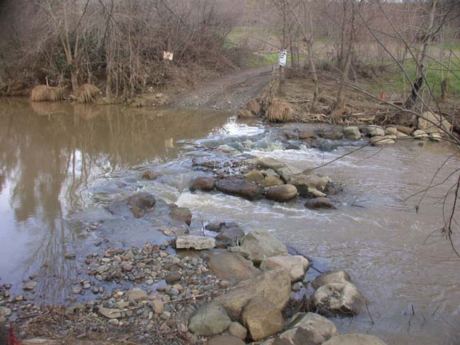
Cross
Vanes in November 2004. Note failure due to lack of footer rocks. |
|
The Bartram Park/Darby Creek Stream Restoration Project improves 427 linear m (1,400 linear ft) of Darby Creek. The focal point of these improvements is the completion of a 34 x 30 x 3 m (110 x 100 x 9 ft) Double Cross Vane that corrects local channel instability. In addition, Boulder Clusters and Spur Dikes provide fish habitat in areas that have little or no flow variation or cover. And finally, over 244 linear m (800 linear ft) of newly planted riparian buffer provide filtration and habitat for fish and other wildlife along Darby Creek.
Please visit the Photo Gallery for more Cross Vane pictures.
18. RESEARCH OPPORTUNITIES
Research opportunities for cross vanes are very similar to those regarding vanes. Vanes constructed from relatively small stone have withstood much higher estimated velocities than adjacent riprap constructed with much larger diameter stone. It is possible that rock vanes, because of their acute angle to the flow, might withstand higher velocities and shear than standard shear equations would predict. More research needs to be done in this area.
Definitive guidance based on scientific tests for determining vane design, including angle, elevation, and spacing is needed. An analysis of scour potential for different substrates with regards to redirective techniques is needed.
19. REFERENCES
Biedenharn, D. S., Elliott, C. M., & Watson, C. C. (1997). The WES Stream Investigation and Streambank Stabilization Handbook. US Army Engineer Waterways Experiment Station, Vicksburg, Mississippi. (pdf)
Brookes, A., Knight, S. S., & Shields, F. D., Jr. (1996). Habitat
enhancement. Chapter 4 in A. Brookes, & F. D. Shields, Jr. (Eds.) River
Channel Restoration. John Wiley and Sons, Chichester, U. K., 103-126.
Genesee/Finger Lakes Regional Planning Council (2001). Cayuga Lake Watershed
Restoration and Protection Plan. Sec: Cayuga Lake Watershed Stream
Restoration, Rock Vanes www.cayugawatershed.org
Greene County Soil & Water Conservation District Stream Restoration Program
(date unknown). Stream Restoration Construction Specifications – SR–02
and SR-03. http://www.gcswcd.com/stream/library/ (pdf
SR-02) (pdf SR-03)
Harman, W., & Smith, R. (2000). Using Root Wads and Rock Vanes for Streambank
Stabilization. River Course, Fact Sheet Number 4, NC A&T State
University, North Carolina Cooperative Extension Service, Raleigh, NC. (pdf)
Johnson, P. A., Hey, R. D., Brown, E. R., & Rosgen, D. L. (2002). Stream
restoration in the vicinity of bridges. Journal of the American Water Resources
Association 38(1):55-67.
Johnson, P. A., Hey, R. D., Tessier, M. & Rosgen, D. L. (2001). Use of Vanes for Control of Scour at Vertical Wall Abutments. Journal of Hydraulic Engineering, 127:3 772-778.
Kuhnle, R. A., Alonso, C. V., & Shields, F. D., Jr. (1999). Volume of scour holes associated with 90-degree spur dikes. Journal of Hydraulic Engineering 125(9):972-978.
Kuhnle, R. A., Alonso, C. V., & Shields, F. D., Jr. (2002). Local scour associated with angled spur dikes. Journal of Hydraulic Engineering 128(12):1087-1093 (pdf)
Maryland Department of the Environment, Water Management Administration (Follweiler, J eds.) (2000). Maryland’s Waterway Construction Guidelines, Section 3 Channel Stabilization and Rehabilitation Techniques, Baltimore, MD. (pdf)
Maynord, S. T. 1995. Corps riprap design guidance for channel protection. In C. R. Thorne, S. R. Abt, F. B. J. Barends, S. T. Maynord, and K. W. Pilarczyk. (eds.). River, coastal and shoreline protection: erosion control using riprap and armourstone. John Wiley & Sons, Ltd., Chichester, U. K., 41-42.
McCullah, J. A. (2004). Bio Draw 3.0. Salix Applied Earthcare,
Redding, CA
Rosgen, D. L. The Cross-Vane, W-Weir and J-Hook Vane Structures. Their Description,
Design, and Application for Stream Stabilization and River Restoration.
Wildland Hydrology, Inc. Pagosa Springs, CO. (pdf)
Rosgen, D. L. (1996). Applied river morphology. Wildland Hydrology Publications,
Pagosa Springs, Colo.
Shields, F. D., Jr., Knight, S. S., & Cooper, C. M. (1995). Incised stream
physical habitat restoration with stone weirs. Regulated Rivers: Research
and Management 10:181-198. (pdf)
Shields, F. D., Jr., Knight, S. S., & Cooper, C. M. (1998). Rehabilitation
of aquatic habitats in warmwater streams damaged by channel incision in Mississippi. Hydrobiologia,
382, 63-86. (pdf)