| VANES WITH J-HOOKS |
|
1. CATEGORY
3.0 – Riparian Buffer and Stream Corridor Opportunities
2. DESIGN STATUS
Level I
3. ALSO KNOWN AS
J-Vanes
4. DESCRIPTION
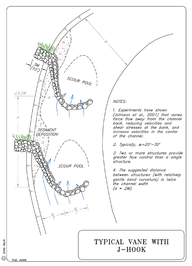
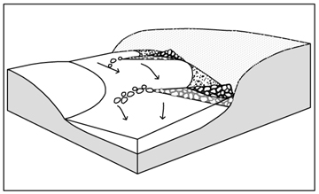
Vanes with J-Hooks are redirective, discontinuous upstream-pointing transverse stone structures with the tips placed in a downstream-pointing "J" configuration. Tips are partially embedded in the streambed so that they are submerged even during low flows. The structures redirect flows away from unstable streambanks, while enhancing aquatic habitat and physical diversity through creation of scour pools.
5. PURPOSE
Vanes with J-hooks, Vanes, and Cross Vanes are all structures that are angled upstream which redirect overtopping flows away from the protected bank (Biedenharn et al., 1997). While vanes are installed to provide toe protection and rectify lateral instability by redirecting flow away from eroding banks, vanes with J-hooks are a variation, with their attendant U-shaped rock structure at the ends, which is intended to produce additional in-stream habitat enhancements. Vanes with J-hooks are useful, especially in gravel to cobble substrates, for creating a scour pool at the “hook” and subsequently producing a riffle below the pool. The center of the channel associated with the hook is efficient at transporting sediment, debris and improving channel capacity and sediment competence (Rosgen, 2001).
When properly positioned, a vane deflects flow away from the bank and induces deposition upstream and downstream of the structure. This redirection of flow reduces velocity and shear stress along the bank while creating a secondary circulation cell that transfers the energy toward the middle of the channel (Fischenich, 2001). Rock vanes, protruding 1/3 bankfull width into the channel and oriented at an upstream angle between 20° and 30°, have been shown to move the thalweg an average of 20% bankfull width away from the eroding bank (Johnson et al., 2001).
Therefore, Vanes with J-Hooks redirect water away from streambanks, into the center of the channel. This serves to decrease shear stress on banks, as well as creating aquatic habitat in the scour pools formed by the redirected flow. By increasing shear stress in the center of the channel, the vanes create a stable width/depth ratio, maintain channel capacity and maintain sediment transport capacity and competence (Rosgen, 2001). J-hook vanes can also be paired and positioned in a channel reach to initiate meander development or migration (Genesee, 2001).
6. PLANNING
Useful for Erosion Processes:
Toe erosion with upper bank failure Scour of middle and upper banks by currents Local scour Erosion of local lenses or layers of noncohesive sediment Erosion by overbank runoff General bed degradation Headcutting Piping Erosion by navigation waves Erosion by wind waves Erosion by ice and debris gouging General bank instability or susceptibility to mass slope failure
Spatial Application:
Instream Toe Midbank Top of Bank
Hydrologic / Geomorphic Setting
Resistive Redirective Continuous Discontinuous Outer Bend Inner Bend Incision Lateral Migration Aggradation Conditions Where Practice Applies:
Vanes with J-Hooks are ideal for treating the outside of stream bends where high velocity and shear stress is causing accelerated bank erosion. Vanes with J-Hooks are simply modified rock vanes and are therefore suitable for use in similar situations. See Vanes for additional information. The ability of vanes to redirect flows and shift local scour and stream power to the center of the channel makes the technique particularly effective where bridge infrastructure is threatened by scour or flanking.
Vanes have been successfully installed in rivers and streams with bankfull widths ranging from 9 to150 m (30 to 492 ft), with gradients between 0.05 to0.0003, and in a variety of bed materials (Rosgen, 2001); it is suggested that they only be used in streams with a width/depth ratio of 12 or greater (Maryland, 2000). This technique should not be used in bedrock streams, those with a highly mobile substrate, or streams that are laterally unstable. It should also be avoided in streams with large sediment or debris loads and those with a gradient steeper than 0.03 (Maryland, 2000; Genesee, 2001).
Complexity:
Moderate.
Design Guidelines / Typical Drawings:
Regardless of project goals, the key design/construction elements of vanes are length, angle, crest elevation, slope, rock size, the placement of appropriate footer rocks, and vane spacing if using the structures in series.
Hydraulic Considerations: The primary hydraulic design consideration for Vanes with J-Hooks is the water surface elevation of bankfull stage (see Special Topic: Bankfull Discharge). Vanes with J-Hooks are independent of design high-water and freeboard, and vegetation establishment is the most common bank protection from bankfull stage to top of bank.
Length: The vane should extend 1/4 to1/3 the bankfull width of the channel (Rosgen, 2001; Maryland, 2000; Brown, 2000). However, this maximum applies to small streams; the larger the channel, the shorter the vane should be relative to the channel width. Untested equations for determining the appropriate length of J-hook vanes based on meander radius of curvature, channel width and vane departure angle are presented in Table 1.
Table 1. Equations for predicting ratio of vane length/bankfull width (VL) as a function of ratio of radius of curvature/width (Rc/W) and departure angle, where W = bankfull width. (SI units)
(Rosgen, 2001)
Rc/W
Departure Angle (degrees)
Equation
3
20
VL = 0.0057 W +0.9462
3
30
VL = 0.0089 W + 0.5933
5
20
VL = 0.0057 W + 1.0462
5
30
VL = 0.0057 W + 0.8462
Angle: Optimum results are obtained when the vane is oriented upstream at an angle with the protected bank between 20° and 30° (Johnson, et al., 2001; Rosgen, 2001). A 20° angle requires a longer vane, but protects a greater length of bank. When orienting vanes for the specific goal of protecting bridge infrastructure, i.e., directing flow through and reducing scour at bridge abutments, a 30° angle is generally more effective at reducing scour at the abutment and moving maximum scour depth toward the center of the channel than the 20° angle (Rosgen, 2001).
Height: The crest elevation of the bank end of the vane should be equal to the bankfull or AHW stage elevation (see Special Topic: Bankfull Discharge). The key into the bank is also designed to bankfull elevation. The vanes must be keyed into the bank at least 3 m (9.84 ft). If the bank is higher than bankfull, Rosgen suggests building a bench at bankfull elevation to key in the vane. David Derrick (personal communication, 2002) and Biedenharn, et al., (1997) recommend overfilling the keyway to counteract settling and subsequent overland flow erosion of the key prior to backfilling. Additional stability and erosion control can be gained by planting the keyway excavations with Willow Poles or Live Siltation. (See Typical Vane Key Detail, Willow Posts and Poles, Live Siltation, and the Special Topic: The Key to Stability is the Key)
Crest Slope: Vanes are designed to be overtopped at the tip by all but the lowest flows and should pitch from the bank to the tip of the vane with a 3-7% slope. Steeper vanes act more like spurs or barbs and have different effects on scour and velocity (Maryland, 2000; Johnson et al., 2001; and Rosgen, 2001).
Rock Gradation and Shape: When possible, vanes should be constructed with graded (self-launching) stone. Self-launching stone will automatically stabilize the toe of the structure in any scour holes that form. Where additional scour is anticipated, more stone may be added to widen the weir crest. In this way, stone may be sacrificed without modifying the crest elevation. The Corps of Engineers has stone gradations for Class A, Class B, and Class C rock (see Special Topic: Self-Launching Stone). Weirs and vanes placed on sand beds devoid of gravel may subside as sand is washed from beneath the stone (Shields et al., 1995); this problem may be addressed by placing filter fabric or a filter layer of finer stone underneath the stone spur.
The Kansas State Conservation Commission has been building vanes and bendway weirs from "shot rock" which generally has a high percent of fines. In very sandy-bottomed streams, it is advantageous to build vanes using "shot rock" or well-graded stone that includes fines, as they prevent ‘through-flow’ of sand, and subsequent scour (McCullah, 2004; P. Balch, personal communication, 2002).
Rocks for J-Hooks: Two types of rock are required: long, flat footer rocks, and angular vane rock. Footer rocks should be relatively long and flat (longest axis should be at least 3.5 times the shortest axis), while the vortex rocks should be both big enough to reach the desired height when buried in the streambed, and be sized to resist movement from shear stress expected from the design flow. Should these criteria conflict, the larger of the two sizes should be used.
When to use footers: The footer rocks should be heavier, longer, and flatter than the average vane rocks. As a rule of thumb, the weight of the heaviest footer rock is comparable to the heaviest rock used for riprap for the design flow (Maryland, 2000; Harman & Smith, 2000). In sandy streams an extra layer of footer rocks may be necessary to compensate for the additional scour. Even in small sand bed streams, 2 m (6.6 ft) of scour next to a structure like this is not uncommon (D. Shields, personal communication, 2004). Empirical formulas are available for scour depth (Kuhnle et al. 1999 and 2002).
Rock Size: The size of the rock will depend upon the stream size and shear stress. See comments below under “Hydraulic Loading” on rock sizing. Some state DOTs (or state resource agencies) have published guidelines for specifying rock size, density and durability. Alternatively, self-launching stone may be used; this will automatically stabilize the toe of the structure in any scour holes that form. Where additional scour is anticipated, more stone may be added to widen the weir crest. In this way, stone may be sacrificed without modifying the crest elevation.
In sand-bed and gravel-bed streams in Kansas vanes have been built without the use of underlying filter fabric or stone footers. In these situations additional rock, intended to self-launch, is incorporated into the design. The additional rock is provided by making the vane crests wider and lower with a much wider ‘footprint’ (2 to 4 m (7 to 13 ft)). The wider crests reduce the chance that the crest elevation will be affected if rock is ‘launched’. Vanes designed with low and wide crests, constructed with very poorly sorted rock, seem to reduce the potential for scour in sand-bed streams (Phil Balch, personal communication, 2002). In very sandy-bottomed streams, it is advantageous to build vanes using “shot rock” or well-graded stone that includes fines, as they prevent ‘through-flow’ of sand, and subsequent scour.
Spacing: The distance from the convergence point of impinging flows along the eroding bank (or upstream corner of a bridge abutment) to the upstream tip of the vane should be twice the channel width (Johnson et al., 2001; Rosgen, 2001). When using vanes in series, the spacing between the upstream tips of the vanes should also be twice the channel width (Maryland, 2000).
Rosgen (2001) suggests the equations in Table 2 for determining appropriate spacing based on meander radius of curvature, channel width and vane departure angle.
Table 2. Equations for predicting ratio of vane spacing/width (Vs) as a function of ratio of radius of curvature/width (Rc/W) and departure angle, where W = bankfull width (SI units) (Rosgen, 2001).
Rc/W
Departure angle (degrees)
Equation
3
20
Vs = - 0.006 W + 2.4781
3
30
Vs = - 0.0114 W + 1.9077
5
20
Vs = - 0.0057 W + 2.5538
5
30
Vs = - 0.0089 W + 2.2067
When using vanes in a series along an outer bend, David Derrick (personal communication, 2000) recommends that the upstream vane be located at the point where impinging flows are first causing erosion. The second vane is located such that the point on the bank that will impacted by the redirected flows are protected by the vane. For small to moderate rivers, less than 20 m wide and where the vane projects approximately 1/3 the width, this spacing is approximately twice the channel width. This method of spacing requires that the design be based the on the flow angles, flow depth and flow direction from the anticipated design storm stage.
As a general rule, small to moderate rivers, less than 20 m (66 ft) wide and where the vane projects approximately 1/3 the width, require spacing that is approximately twice the channel width.
7. ENVIRONMENTAL CONSIDERATIONS / BENEFITS
Vanes with J-Hooks may be used as habitat improvement structures. Rosgen (2001) presents a partial list of potential positive effects on stream habitats:
Increase in bank cover due to an increase in water level at the bank above the weir.
Creation of holding pools and refuge cover in the scour pool during high and low flows.
Creation of "feeding lanes" for fish at the interface between fast and slow moving water. This is created where the high-energy flow in the center of the channel interacts with the calm water surrounding the scour pool.
Other benefits of Vanes with J-Hooks include improved benthic habitat, creation or maintenance of pool and riffle habitat, improved fish rearing habitat, and holding areas for adult fish.
8. HYDRAULIC LOADING
Allowable hydraulic loading is related to stone size. Considerable velocity and shear stress can be withstood if rocks are large enough. However, extremely large rock may be unavailable, and can be difficult to place with available equipment. Also, rock much larger than channel bed material will trigger local scour problems.
Permissible shear and velocity for cross vanes is related to the size of rock used in construction. Other factors, such as the angularity of the stone, the thickness of the layers of stone, and the angle at which the faces of the stone structure are constructed also come into play. Detailed guidance for sizing stone for bed and bank stabilization structures is beyond the scope of this guideline, and many approaches are available (see Special Topic: Designing Stone Structures). However, the Maynord (1995) equation gives a D50 stone size for an angular stone riprap revetment of 0.875 m (2.9 ft) if the near-bank vertically-averaged velocity is 3.5 m/s (11.5 ft/s), and flow depth = 1 m (3.3 ft), and stone is placed on a bank slope of 1V:1.5H. Use of riprap larger than this is unusual.
9. COMBINATION OPPORTUNITIES
Since rock vanes can successfully reduce near-bank velocities and shear stress, vegetation establishment is greatly improved. Vanes are often combined with other biotechnical soil stabilization measures for bank areas between the vanes. Vegetated ground cover techniques such as Turf Reinforcement Mats, Erosion Control Blankets, Live Stakes, Live Brush Mattress, and Vegetation Alone are appropriate candidates for combination. Rock vanes are occasionally used in conjunction with continuous and resistive armoring measures, such as Cobble or Gravel Armor, Vegetated Riprap or Longitudinal Stone Toe, when additional protection between the vanes is required. Live Brushlayering, Willow Poles, and Live Siltation are extremely effective when implemented at the bank during excavation of the keyways. Posts and Poles can be used create overhanging cover for pools up- or downstream from cross vanes (Shields et al., 1995).
10. ADVANTAGES
Rosgen (2001) lists the advantages of Vanes with J-Hooks as follows:
Vanes with J-Hooks decrease velocity, shear stress and stream power adjacent to the bank, and increase them in the center of the channel. Sediment transport competence and capacity are maintained as a result of the increased shear stress and stream power in the center third of the channel, where the J-Hook is located. Backwater occurs adjacent to the bank, encouraging sediment deposition in the near-bank areas, and reducing active bank erosion (Rosgen, 2001).
The scour pool in the center third of the channel provides energy dissipation and holding cover for fish (Rosgen, 2001). The flow separation zones that mark the zones of down- and upwelling currents are valuable aquatic habitat. The "hook" portion of the vane produces a longer, wider and deeper pool than that created by simple vane structures. The center of the channel associated with the hook is efficient at transporting sediment, debris and improving channel capacity and sediment competence. The "shooting flow" associated with the hook portion of the structure provides for recreational boating in moderate to larger sized rivers. Width/depth ratios are maintained by decreasing bank erosion rate and increasing bankfull channel depth, even following major floods (Rosgen, 2001).
11. LIMITATIONS
This technique should not be used in bedrock streams, those with highly unstable beds, or streams that are laterally unstable. Vanes with J-Hooks should also be avoided in streams with large sediment or debris loads and those with a gradient steeper than 3% (Maryland, 2000; Genesee, 2001).
For the technique to function properly, velocity should not be below 0.25 m/s (0.8 ft/s) for extended periods.
Some additional land loss through bank retreat is likely to occur during and after construction before a stable bank configuration is reached.
This technique is best applied only where the floodplain width is more than twice as wide as the average channel width. (Here channel width is the width of the active channel, and floodplain is the surface flooded with a frequency of 50 to 100 years.)
This technique is only for channels wider than 15 m (49 ft).
This technique should be used in beds with coarser sediments like gravel or cobble.
There are no restrictions on the use of this technique based on streambank material.
This technique should be used only at sites where the probability of loss of life or severe damage to adjacent structures due to failure of this project is very small.
This technique is possibly suited for braided streams.
This technique may be successfully applied in reaches classified as Stage V or VI, or where there is no channel incision present in the watershed.
12. MATERIALS AND EQUIPMENT
Vanes with J-hooks are generally constructed with poorly sorted, graded rock however, successful vanes have also been constructed from single logs and log cribs with stone fill (Brown, 2000; Rosgen, 2001). Regardless of the material comprising the vane arms, the “hook” portion should be constructed of rock (see Rocks for J-hooks above). An excavator or backhoe is usually needed to construct the keyways and is the most effective equipment to use for rock placement.
13. CONSTRUCTION / INSTALLATION
Construction will require excavation of key into the bank at minimum of 3 m (10 ft) to a height of bankfull elevation. If the bank is higher than bankfull, Rosgen suggests building a bench at bankfull elevation to key in the vane. The keyways should be constructed by digging a trench, placing rock and installing vegetation (as described in Willow Posts and Poles), and backfilling. If vegetative techniques are used, such as Willow Post and Poles or Live Siltation, the chances of successful establishment can be increased by "watering in" the cuttings.
 |
 |
Self launching rock can be placed on the existing substrate however, if footer rocks are necessary then excavation of the trench for the footer rocks will be required. The depth of the trench varies depending on bed material. For a gravel or cobble bed stream, a depth of twice the diameter of the average vane rock is recommended for the footer trench (Rosgen, 2001; Maryland, 2000). The footer rocks should be placed with a gap between the stones equal to 1/3 their diameter which allows them to interlock as the vane adjusts and equilibrates (Rosgen, 2001). In sandy bed material, or where excessive scour is predicted, the trench depth should be four times the diameter of the average vane rock and the gaps between the rocks should be eliminated. It may be feasible to place a filter fabric geotextile under the footer stones on sand-bed streams. See Rock Gradations above.
When placing the rocks, ensure that the top rocks are placed on top of footer rocks such that each top rock touches adjacent rocks and rests upon two halves of each footer rock below it, and so that the top rock is offset in the upstream direction. Rocks should be shingled upstream.
14. COST
Limited actual cost data could be located so a reasonable relative cost to riprap for Vanes with J-Hooks is estimated to be 0.5. It is assumed that under appropriate conditions, vanes can provide protection equivalent to rock riprap at approximately 1/2 the cost which is estimated at $148.00 per linear m ($46.25 per linear ft) of bank. Rosgen (2001) notes that a vane protects a minimum bank length of twice the vane length and this observation has been verified and demonstrated in several instances.
Two (2) vanes with J-hooks were installed on Manatawny Creek in Pottstown, PA. The total cost for these including materials, labor, and design was $108.89 per linear foot.
15. MAINTENANCE / MONITORING
The J-Hook Vane should be inspected regularly. Maintenance staff should determine:
16. COMMON REASONS / CIRCUMSTANCES FOR FAILURE
Unintended impacts can result from improper design and construction. Structures built with unsuitable gradation or undersized stone may unravel (stones from the crest may be scoured and transported away). If the vane is not properly keyed into the bank, it is likely to fail, creating new localized erosion problems (Rosgen, 2001). Improper vane angle and height can redirect flow to unintended places, creating further bank erosion downstream of the structures (Johnson, 2001). Some failures are related to undermining or flanking by scour (surface erosion) or seepage under and around the structure (subsurface erosion). The most prevalent problem with vanes with J-hooks is the "hook" structure may become undermined and fail into the downstream scour hole. This is usually a result of improper footer stone placement.
17. CASE STUDIES AND EXAMPLES
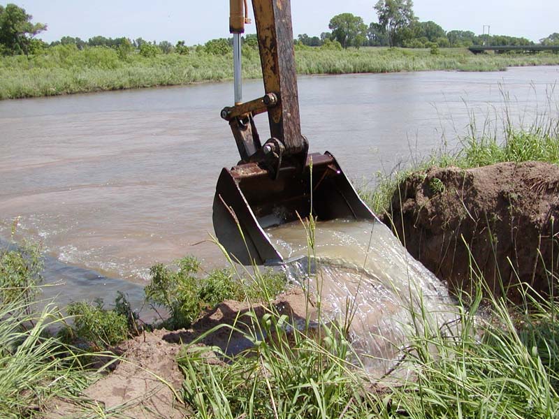
Manatawny Creek, Pottstown, PA
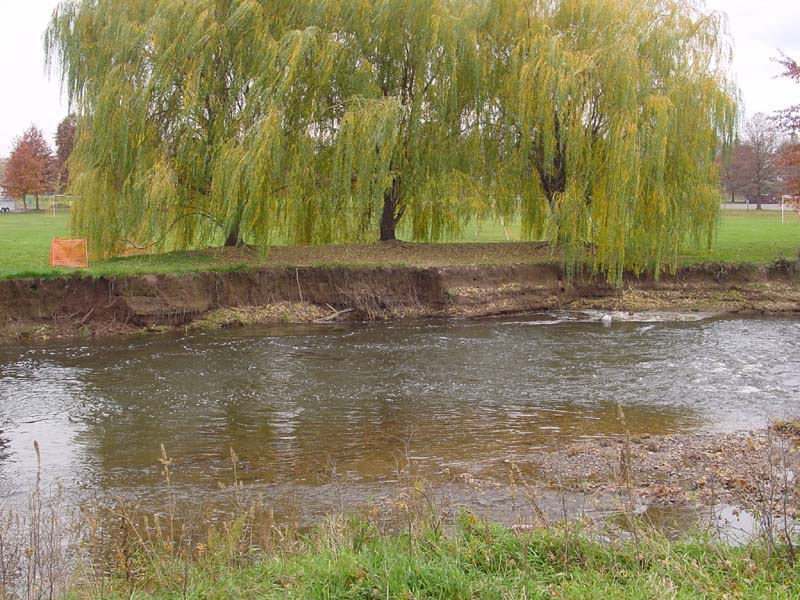
Two (2) vanes with J-hooks were installed on Manatawny Creek in Pottstown, PA. The structures were installed in succession on the right bank of the stream in late fall of 2002. Photos courtesy of Delaware Riverkeeper Network.
 |
 |
|
View upstream of the J-hook
installation on Manatawny creek. |
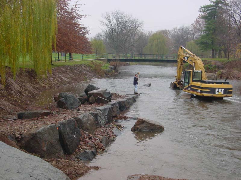
 |
 |
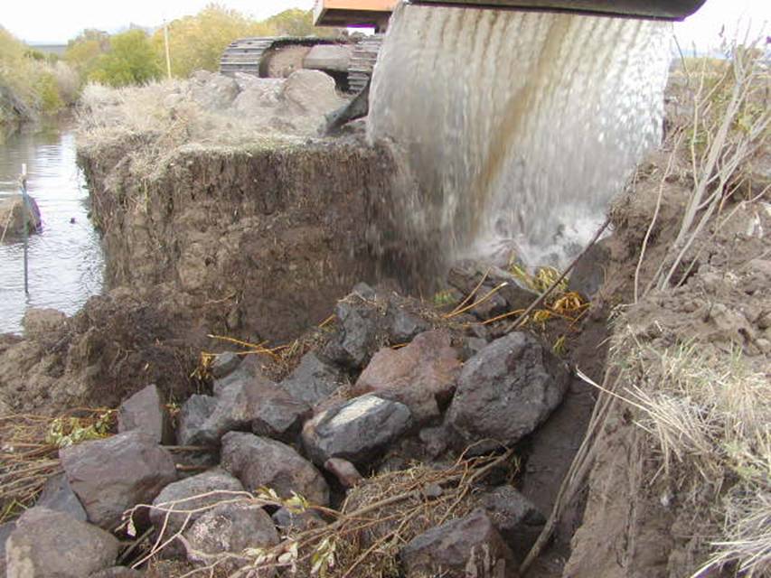
View upstream immediately
following project installation on Manatawny Creek. Note the flow
pattern of the stream as it approaches and is directed to the center
of the channel by the structure. |
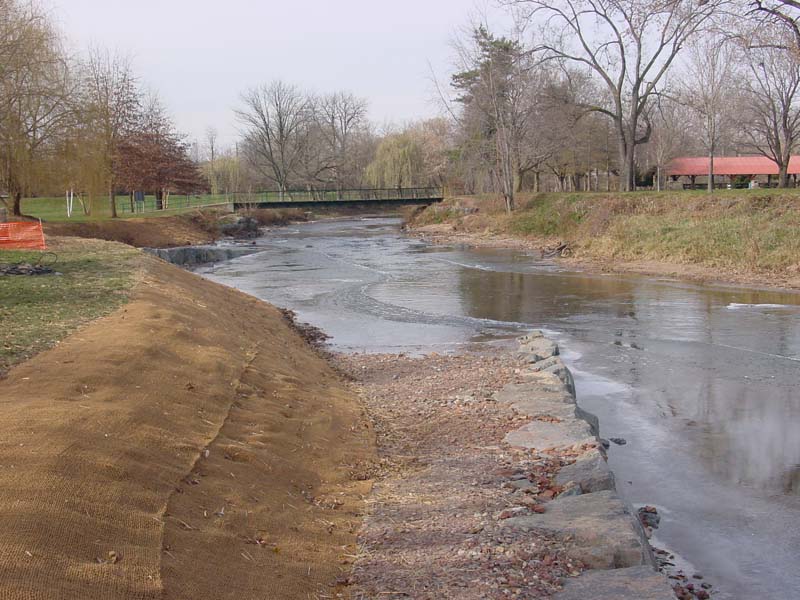
View downstream of the finished
project on Manatawny Creek. The two J-hooks were installed and the
bank was also stabilized with geotextile blankets and straw. Seed
was also applied. |
Please visit the Photo Gallery for more pictures.
18. RESEARCH OPPORTUNITIES
Hydraulic loading information and cost data for J-Hook vanes would be of great help in designing these structures. Design criteria based on flume experiments or numerical simulations are needed to confirm or replace the empirical Rosgen relations.
19. REFERENCES
Biedenharn, D. S., Elliott, C. M. & Watson, C. C., 1997. The WES Stream Investigation and Streambank Stabilization Handbook. US Army Engineer Waterways Experiment Station, Vicksburg, Mississippi
Brown, K. (2000). Urban Stream Practices: An Initial Assessment. Center for Watershed Protection, Ellicott City, MD. (pdf)
Fischenich, J. C. (2001). Impacts of stabilization measures. EMRRP Technical Notes Collection (ERDC TN-EMRRP-SR-32), U.S. Army Engineer Research and Development Center, Vicksburg, MS (pdf)
Genesee/Finger Lakes Regional Planning Council (2001). Cayuga Lake Watershed Restoration and Protection Plan. Sec: Cayuga Lake Watershed Stream Restoration, Rock Vanes www.cayugawatershed.org
Harman, W., and Smith, R. 2000. Using Root Wads and Rock Vanes for Streambank Stabilization. River Course, Fact Sheet Number 4, NC A&T State University, North Carolina Cooperative Extension Service, Raleigh, NC.
Johnson, P. A., Hey, R. D., Brown, E. R., & Rosgen, D. L. (2002). Stream restoration in the vicinity of bridges. Journal of the American Water Resources Association 38(1):55-67.
Kuhnle, R. A., Alonso, C. V., & Shields, F. D., Jr. (1999). Volume of scour holes associated with 90-degree spur dikes. Journal of Hydraulic Engineering 125(9):972-978.
Kuhnle, R. A., Alonso, C. V., & Shields, F. D., Jr. (2002). Local scour associated with angled spur dikes. Journal of Hydraulic Engineering 128(12):1087-1093 (pdf)
Maryland Department of the Environment, Water Management Administration (Follweiler, J eds.) (2000). Maryland’s Waterway Construction Guidelines, Section 3 Channel Stabilization and Rehabilitation Techniques, Baltimore, MD. (pdf)
Maynord, S. T. (1995). Corps riprap design guidance for channel protection. In C. R. Thorne, S. R. Abt, F. B. J. Barends, S. T. Maynord, and K. W. Pilarczyk. (eds.). River, coastal and shoreline protection: erosion control using riprap and armourstone. John Wiley & Sons, Ltd., Chichester, U. K., 41-42.
McCullah, J. A. (2004). Bio Draw 3.0. Salix Applied Earthcare, Redding, CA
Rosgen, D. L. (2001). The Cross-Vane, W-Weir and J-Hook Vane Structures. Their Description, Design, and Application for Stream Stabilization and River Restoration. Wildland Hydrology, Inc. Pagosa Springs, CO. (pdf)
Shields, F. D., Jr., Knight, S. S., & Cooper, C. M. (1995). Incised stream physical habitat restoration with stone weirs. Regulated Rivers: Research and Management 10:181-198. (pdf)