| LIVE GULLY FILL
REPAIR |
 |
| LIVE GULLY FILL
REPAIR |
|
1. CATEGORY
3.0 – Riparian Buffer and Stream Corridor Opportunities
2. DESIGN STATUS
Level III
3. ALSO KNOWN AS
Gully fill and re-vegetation.
4. DESCRIPTION
In general, gully repair consists of a combination of techniques for stabilizing eroding intermittent or ephemeral channels. These repair techniques taken together include grading, installing drainage and fill, live cuttings, and surface erosion control. Live Gully Fill Repair (Gray and Sotir, 1996) consists of alternating layers of live branch cuttings and compacted soil. This reinforced fill can be used to repair small gullies. The method is similar to branch packing (a method for filling small holes and depressions in a slope) but is more suitable for filling and repairing elongated voids in a slope, such as gullies. Gully treatment must include correcting or eliminating the initial cause of the gully as well as the gully itself. Accordingly, consideration should be given to diverting excessive or concentrated runoff away from the gully head area (see Techniques: Drop Inlet, Slope Drain, Trench Drain, and Diversion Dike). Gullies are likely to have side gullies that require treatment; however, priority should be given to the main channel.
5. PURPOSE
Gully erosion is complex and involves multiple processes that can occur at the same time (Schumm et al., 1984). Gully erosion is caused by channel downcutting (or incision), headcutting, and mass wasting of gully sides. Effective gully treatment and control requires an understanding of each process acting individually and/or in tandem (Heede, 1976). The purpose of gully erosion control, in general, is to arrest and /or mitigate these degradational processes. Live gully fill repair is intended primarily as a technique for filling the gully channel and restoring the original slope topography. Filling also counteracts mass wasting of the gully sides and spring sapping at the gully head. Filling will only be successful, however, if the fill is suitably reinforced, seepage and overland flow into the gully diverted or intercepted, and the gully base level at its lower end stabilized by a check dam and/or drop inlet.
6. PLANNING
Useful for Erosion Processes:
Toe erosion with upper bank failure Scour of middle and upper banks by currents Local scour Erosion of local lenses or layers of noncohesive sediment Erosion by overbank runoff General bed degradation Headcutting Piping Erosion by navigation waves Erosion by wind waves Erosion by ice and debris gouging General bank instability or susceptibility to mass slope failure
Spatial Application:
Instream Toe Midbank Top of Bank
Hydrologic / Geomorphic Setting
Resistive Redirective Continuous Discontinuous Outer Bend Inner Bend Incision Lateral Migration Aggradation Conditions Where Practice Applies:
Live Gully Fill Repair is useful for gullies ranging in depth from about 0.3 to 2 m (1 to 6 ft) deep to 10 m (30 ft) long. This repair technique should only be used in channels with intermittent flows. The erosion processes at work in the incised channel, or "gully", must be correctly identified and understood to make a successful repair. For example, headcutting (erosion at a knickpoint) from a culvert might be stabilized with a drop structure. Grade control can be employed at the low end of the channel or at side gullies by using a check dam or drop inlet (see Technique: Drop Inlet). Side slopes might be graded back (see Technique: Slope Flattening), stabilized with vegetation, and the surface runoff slowed with wattles. The center channel may require installation of subdrains if substantial runoff or seepage flows cannot be diverted.Complexity:
Moderate. This technique is not difficult to implement and is similar to live brushlayering with the main difference being its placement in a confined channel.
Design Guidelines / Typical Drawings:
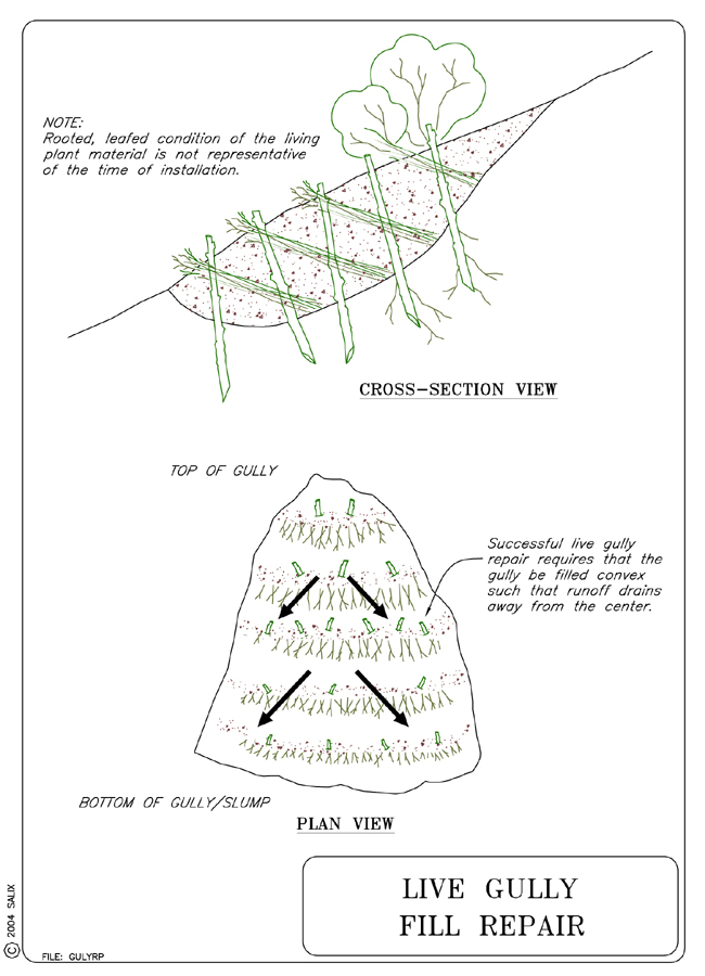
This technique should be used to fill small gullies in natural slopes and streambanks. Fill placed in the channel should consist of graded and well drained soil. Imbedded branches and their secondary roots will reinforce the backfill used to repair the gully and protect it against future washout and scour. A subsurface drain may be required if significant amounts of seepage or groundwater enters the gully at its head (see Technique: Fascines with Subsurface Drain). Surface runoff entering the gully at its head should be intercepted and diverted away from the area (see Technique: Diversion Dike). The main details of a live gully fill repair are shown in Figure 1.
7. ENVIRONMENTAL CONSIDERATIONS / BENEFITS
Gullying is promoted by continued activation and incision resulting from
downcutting and base level lowering at the confluence of a stream and a tributary
gully system. Stabilization of the main gully at its confluence with a stream
or river is an essential first step in controlling development of an extensive
gully network that may be associated with the main gully. Gully stabilization
and repair helps to restore the original slope topography and to decrease
sediment loading from the gully to a connected stream.
8. HYDRAULIC LOADING
The same considerations governing permissible hydraulic loading of Live
Brushlayers also govern hydraulic loading of Live Gully Fill Repair, at least in those
cases where the repair fill in a tributary gully is subjected to shear stresses
and flow velocities in a connecting stream.
9. COMBINATION OPPORTUNITIES
Live Gully Fill Repair can be used in combination with virtually any in-stream,
toe, and mid-bank stabilization or protection technique. The use of additional
reinforcement of soil lifts with geotextile or geogrid wraps may be considered
in steep, critical gully channels (see Technique: Vegetated
Mechanically Stabilized Earth). Other ancillary techniques
include the following: Diversion
Dikes, Slope
Drains, Drop
Inlets, and Trench
Drains.
10. ADVANTAGES
Corrects and eliminates a significant source of sediment loading to a stream.
11. LIMITATIONS
Subject to washout and scour if excessive groundwater or runoff saturates
fill.
12. MATERIALS AND EQUIPMENT
Graded and well drained soil for use as fill material. Live branch cuttings
ranging from 1.2 cm to 4.4 cm (0.5 in to 2 in) in diameter. The branches should
be long enough to touch the undisturbed soil at the bottom (back) of the gully
and to protrude slightly beyond the rebuilt slope face.
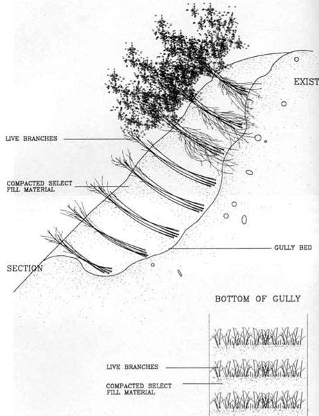
Figure 1. Schematic drawing of established live gully
fill repair (from Gray and Sotir, 1996)
13. CONSTRUCTION / INSTALLATION
Live Gully Fill Repair begins at the lowest point in the gully and proceeds upward. The live branches are inserted between successive lifts of lightly compacted soil. The following guidelines and procedures (Gray and Sotir, 1996) are recommended when installing a live gully fill repair system:
Starting at the lowest point of the slope, place a 3- to 4-in thick layer of branches at the lowest end of the gully and approximately perpendicular to the gully bottom (see Figure 1).
Cover with a 6- to 8-in thick layer of fill soil and compact.
Place the live branches in a crisscross fashion. Orient the growing tips toward the slope face with the basal ends lower than the growing tips.
Follow each layer of branches with a layer of soil; work and compact the soil to ensure intimate contact with the branches and to eliminate large voids in the fill.
14. COST
Information not available, but should be comparable to Live Brushlayering.
15. MAINTENANCE / MONITORING
Periodically check on stability of gully fill, particularly during the initial
vegetative establishment period. Check for wet spots or seeps in fill which
indicate subsurface seepage problems. Examine surface of fill for evidence
of runoff erosion such as rills. Make sure that runoff is diverted away
from fill during initial stages.
16. COMMON REASONS / CIRCUMSTANCES FOR FAILURE
The main reason for failure of a live gully fill repair is saturation and
washout of the earthen fill. Prevention of this outcome requires that seepage
and runoff be excluded as much as possible from the fill area.
17. CASE STUDIES AND EXAMPLES
Information Unavailable
18. RESEARCH OPPORTUNITIES
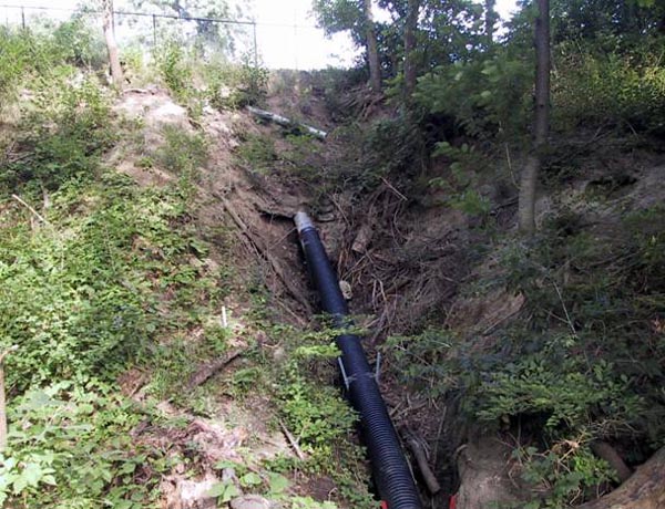
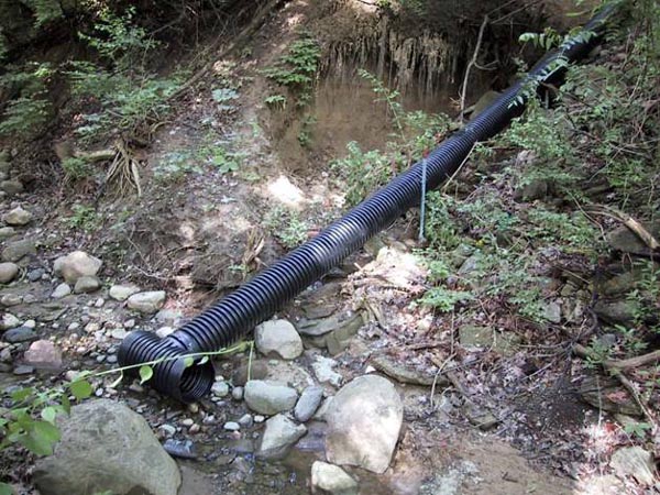
The conjunctive use of buried, flexible slope drains with Live Gully Fill Repair (see Technique: Slope Drains). This approach would entail placing a flexible pipe drain on the gully bottom, surrounding (encasing) it with a protective granular filter layer, and then installing the Live Gully Fill Repair on top of the buried slope drain. An example of such a solution is shown in the photos below, where a flexible, corrugated pipe has been attached to a culvert discharge pipe located near the top of a high streambank. The discharge from the culvert high on the slope caused a major tributary gully to develop in the bank as shown in the Figure 2 and 3. The flexible slope drain now conveys this discharge safely to the stream channel below and would permit the placement of a live gully fill repair atop the pipe.
|
|
Please visit the Photo Gallery for more pictures.
19. REFERENCES
Gray, D. H. & Sotir, R. (1996). Biotechnical and Soil
Bioengineering Slope Stabilization. John Wiley and Sons, New York, N.
Y.
Heede, B. H. (1976). Gully Control and Development. USDA Forest
Service. Research Paper RM-169, Rocky Mtn. Forest and Range Experiment
Station, Ft. Collins, CO, 49 pp.
Schumm, S. A., Harvey, M. D., & Watson, C. C. (1984). Incised channels: Morphology, dynamics and control. Water Resources Publications, Littleton, Colo.