| DROP INLET |
 |
| DROP INLET |
|
1. CATEGORY
4.0 – Slope Stabilization
2. DESIGN STATUS
Level II
3. ALSO KNOWN AS
Drop pipes, riser pipes, minor grade control structures.
4. DESCRIPTION
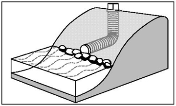
Concentrated overbank runoff can be a major cause of erosion, especially along deeply incised channels. Runoff passing over the top of banks frequently triggers gully development and expansion, and water that is ponded at the top of high, steep banks, and infiltrates or seeps into the ground behind the slope face is often a major factor in erosion by piping or slope failure from the development of high pore water or seepage pressures. The gully erosion and downcutting can be addressed using a drop inlet, which is a water control structure that consists of an L-shaped corrugated pipe passing through an earthen embankment placed at the downstream end of the gully.
5. PURPOSE
Drop Inlets and their associated embankment (dam or dike) retain runoff on the edge of fields, allow sediment deposition at field level where it may be reclaimed, and dissipate excessive runoff energy as flow is conducted down to channel level through the pipe. Gully advancement for properly designed structures is essentially halted in this manner.
6. PLANNING
Useful for Erosion Processes:
Toe erosion with upper bank failure Scour of middle and upper banks by currents Local scour Erosion of local lenses or layers of noncohesive sediment Erosion by overbank runoff General bed degradation Headcutting Piping Erosion by navigation waves Erosion by wind waves Erosion by ice and debris gouging General bank instability or susceptibility to mass slope failure
Spatial Application:
Instream Toe Midbank Top of Bank
Hydrologic / Geomorphic Setting
Resistive Redirective Continuous Discontinuous Outer Bend Inner Bend Incision Lateral Migration Aggradation Conditions Where Practice Applies:
Used where large amounts of surface runoff flow across a steep high, streambank along an existing tributary gully or small ravine. Small amounts of overbank runoff flowing across a relatively intact or non-incised bank crest are best handled with a diversion dike and slope drains.Complexity:
High. Drop inlets are relatively complex to design and construct because the system requires construction of a containment embankment (dam) in addition to correctly sizing the pipe to convey calculated runoff volumes.
Design Guidelines / Typical Drawings:
The following criteria are based on practices employed by the U.S. Army Corps of Engineers and the Natural Resources Conservation Service in the Southeast USA (Trest, 1997). Additional information is available from Goldman et al. (1986).
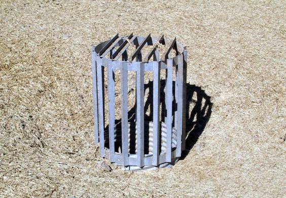
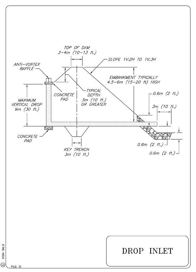
Drop pipe structures are generally placed in gullies deeper than 3 m (10 ft), and embankments are typically 4.5 to 6 m (15 to 20 ft) high. Minimum safety factors for embankments are 1.3, dictating side slopes of 1:2 to 1:3 (V:H). Pipes are sized to convey the 2- to 10-year event based on standard SCS runoff curve number computations, and an emergency spillway is provided to convey flows larger than the design discharge. Design discharges are typically less than 5.7 m3/s (200 cfs), and the vertical distance from the inlet weir crest to the outlet pipe invert is less than 9 m (30 ft). Pipe diameter and length are used to compute head-discharge relations, and pipe diameter is adjusted to avoid orifice flow at discharges less than or equal to design flow. Drop pipes may be designated non-storage structures, which are sized to pass the two- to five-year event, or as temporary storage structures, which are designed to impound runoff from the 25-year event. Water retention is governed by site factors (soils, topography, water supply) and by the elevation of the inlet weir and emergency spillway. A schematic drawing of a drop inlet structure is shown in the Typical Drawing.If uncontrolled erosion occurs in the drainage area behind the slope crest, the runoff may carry large amounts of sediment. A drop inlet can convey this sediment-laden runoff directly into an adjoining stream. If erosion is extensive, the drain itself may clog and lose a significant portion of its capacity. In these cases, sediment should be prevented from entering the drop inlet by providing some type of filtering and/or inlet protection, either filter fabric, gravel & wire mesh, or block and gravel sediment barrier. A photograph of a trash rack used to prevent large debris from entering and clogging a drop pipe is shown in Figure 1. Goldman et al. (1986) provide detailed guidance for the design and installation of these inlet protection systems.
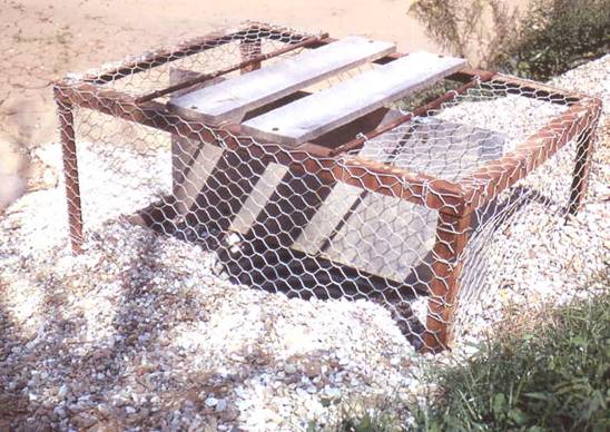
Pipe materials can be aluminized or galvanized polymer-coated metal or polymeric materials. Seepage through the earthen embankment is controlled with seepage collars for structures with conduits 1.2 m (4 ft) in diameter or smaller, and with annular filter drainage rings for larger conduits. Where the structure will impound water permanently, a filter drainage diaphragm is used. Concrete pads are provided at the top and bottom of the vertical pipe, and an anti-vortex baffle is placed in the inlet to maintain weir flow and avoid vibration during very large events (see Figure 2). Outlets are supported with grouted riprap and secured with screw anchors. In addition, stone erosion protection is provided at the outlet for structures larger than 1.2 m (4 ft) in diameter.
Figure 1. Metal trash rack used to protect drop inlet.
Figure 2. Drop inlet pipe with anti-vortex baffle and trash rack.
7. ENVIRONMENTAL CONSIDERATIONS / BENEFITS
Embankments, pools, and entry and exit channels associated with drop pipes
partially replace riparian corridor habitats, such as streamside wetlands.
Drop pipe structures often create wetland habitats for fish, amphibians, reptiles,
birds, and mammals; 75 vertebrate species were reported in one series of studies
(Shields et al., 2002). Water quality and sediment quality conditions in drop
pipe pools appear adequate for aquatic and semi-aquatic species of plants
and animals; generally, better water quality is found in deeper pools. Habitat
quality associated with drop inlets can be increased considerably by designing
inlets so that a permanent pool is maintained, woody vegetation is allowed
to develop, and a minimum of 0.1 ha (0.25 acre) is maintained adjacent to
the inlet as undisturbed or rarely disturbed habitat (Shields et al., 2002).
8. HYDRAULIC LOADING
Hydraulic loading is not a factor in the design/installation of drop inlets
because the pipe is placed (buried) within the containment dike (dam) and
is not exposed to shear or tractive stresses of streamflow. The main hydraulic
consideration is that the inlet pipe has sufficient capacity (diameter)
to handle expected runoff volumes. There will be some hydraulic loading
on the exit end of the drop inlet pipe where it daylights into the stream
channel. This will require some stone or rock armoring protection as shown
in the Typical Drawing (see also discussion in section on design guidelines).
9. COMBINATION OPPORTUNITIES
Ditches and drains intercept local overland flow and direct it to the drop
inlet (see Technique: Diversion
Dike). Suitable inlet protection (sediment barriers) should
be used where runoff carries large amounts of sediment in suspension.
On a larger scale, drop inlets are typically part of a system-wide treatment
of all incising channels within a watershed as described by Shields et
al. (1999). A gully treatment program (see Technique: Live
Gully Repair) can be used to repair and mitigate problems
in the upstream reaches of a gully network once a local base level has
been established at the downstream end by means of a drop inlet and dam
structure.
10. ADVANTAGES
A drop inlet structure conveys concentrated runoff safely down incisions
(tributary gullies or shallow ravines) in steep, high streambanks and stops
further headcutting in the gully or ravine. It also can attenuate or greatly
decrease sediment loading to the stream from a tributary gully system. A
drop inlet can be designed and constructed to handle much larger runoff
flows that a diversion dike and slope drain system.
11. LIMITATIONS
Trash and debris can clog the intake which can lead to possible overtopping
of the containment embankment or dam. Excessive sediment in the runoff can
be conveyed to the stream channel below in the absence of suitable filtering
at the inlet and/or a long enough residence time for the sediment to drop
out in the ponded area behind the embankment dam. Ponding of water atop a
streambank can exacerbate piping and seepage related bank instability.
12. MATERIALS AND EQUIPMENT
Earthmoving equipment and standard erosion control measures are needed for
construction of the embankment. A source of fill for the dam is needed, and
pipes, trashracks, and stone for scour protection are essential materials.
Pipe materials can be aluminized or galvanized polymer-coated metal or polymeric
materials.
13. CONSTRUCTION / INSTALLATION
See Trest (1997) and Goldman et al. (1996).
14. COST
Costs for drop inlets are highly site-specific, as the size and complexity of earthen embankment construction varies with the size of the gully and depth of the adjacent stream channel, as well as the proximity of suitable soil for fill.
15. MAINTENANCE / MONITORING
Clogging of the inlet can be prevented by periodic inspection of the entrance
protection structure or trash rack (see Figure 1 and 2). If sediment in
the pond behind the dam accumulates to the base of the pipe entrance, it
may be necessary to raise the entrance elevation of the pipe. A gully treatment
program in the upstream reaches of the gully or gully network (see Technique:
Live Gully
Repair) can also be employed to reduce sediment loading.
16. COMMON REASONS / CIRCUMSTANCES FOR FAILURE
Clogging of the down-pipe can lead to possible overtopping of the containment
embankment and erosion of the downstream face of the dam in the absence
of a properly designed emergency spillway. Excessive sediment in the runoff
can be conveyed to the stream channel below in the absence of suitable filtering
at the inlet and/or a long enough residence time in the ponded area behind
the embankment dike. Ponding of water atop a streambank can exacerbate piping
and seepage related bank instability. This latter problem is minimized,
however, if the embankment and pond are located at the downstream end of
the gully and if pond water levels are maintained as low as possible.
17. CASE STUDIES AND EXAMPLES
See Shields et al. (2002) and Trest (1997).
18. RESEARCH OPPORTUNITIES
Information Unavailable
19. REFERENCES
Goldman, S. J., Jackson, K., & Bursztynsky, T. A. (1986). Erosion
and sediment control handbook. McGraw Hill, New York. pp 7.237.27 and
8.618.66.
Shields, F. D., Jr., Brookes, A. & Haltiner, J. (1999). Geomorphological
Approaches to Incised Stream Channel Restoration in the United States and
Europe,” Chapter 14 in Darby, S. E. and Simon, A. (eds.), Incised
River Channels: Processes, Forms, Engineering and Management. John
Wiley & Sons, New York, 371-394.
Shields, F. D., Jr., Smiley, P. C., Jr., & Cooper, C. M. (2002). Design
and Management of Edge-of-Field Water Control Structures for Ecological
Benefits. Journal of Soil and Water Conservation 57(3), 151-157.
(pdf)
Trest, J. W. (1997). Design of structures for the Yazoo Basin Demonstration Erosion Control Project. In: Wang, S. Y., E. Langendoen, and F. D. Shields Jr. (eds). Management of landscapes disturbed by channel incision: stabilization, rehabilitation, and restoration. Center for Computational Hydroscience and Engineering, University of Mississippi, 1017-1022.