| DIVERSION
DIKE |
 |
| DIVERSION
DIKE |
|
1. CATEGORY
4.0 – Slope Stabilization
2. DESIGN STATUS
Level II
3. ALSO KNOWN AS
Interceptor, diversion, slope runoff diversion.
4. DESCRIPTION
A diversion dike is a low berm (or ditch and berm combination) that is constructed along the crest or top of a streambank.
5. PURPOSE
The purpose of a diversion is to intercept and divert runoff away from the face of a steep slope or streambank (USDA, 1972; Gray and Sotir, 1996). Diverted runoff should outlet onto a stabilized area, a prepared level spreader, or into a slope protection structure, e.g., a slope drain. Diversion dikes are constructed from compacted earthen fill and should be used on drainage areas of 2 ha (5 acres) or less. In addition to protecting the face of a streambank from overbank runoff, diversions may also improve general slope stability by preventing runoff from infiltrating and saturating the face of the bank.
6. PLANNING
Useful for Erosion Processes:
Toe erosion with upper bank failure Scour of middle and upper banks by currents Local scour Erosion of local lenses or layers of noncohesive sediment Erosion by overbank runoff General bed degradation Headcutting Piping Erosion by navigation waves Erosion by wind waves Erosion by ice and debris gouging General bank instability or susceptibility to mass slope failure
Spatial Application:
Instream Toe Midbank Top of Bank
Hydrologic / Geomorphic Setting
Resistive Redirective Continuous Discontinuous Outer Bend Inner Bend Incision Lateral Migration Aggradation Conditions Where Practice Applies:
Diversion dikes should be used only on drainage areas of 2 ha (5 acres) or less.Complexity:
Diversion dikes are relatively simple to construct. They require only a small amount of earthwork and can be constructed either by hand or with a small backhoe.
Design Guidelines / Typical Drawings:
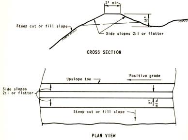
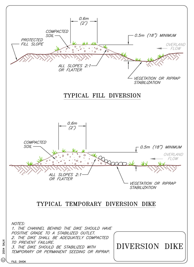
Diversion dikes are constructed from compacted earthen fill to a height of 45 cm (18 in) with side slopes 1V:2H or flatter. Height is measured from the upslope toe to the top of the dike (see Figure 1).
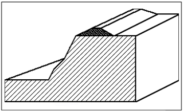
Figure 1. Cross section and plan views of diversion dike
Figure 2. Diversion dike used in combination with a flexible slope drain
The dike should have a minimum top width of 60 cm (2 ft). A conceptual design for a diversion dike, either a berm only or a berm and ditch combination is shown in Figure 1. A shallow trench or swale to contain the diverted runoff is normally incorporated into the design. Soil from the ditch can be used to construct the berm, provided it has sufficient fines to hold a 1V:2H side slope and be relatively impermeable when compacted. The swale or drainage ditch must have positive drainage to an outlet. Vegetative or mechanical stabilization may be required where grades are excessive.
7. ENVIRONMENTAL CONSIDERATIONS / BENEFITS
Interception and collection of runoff behind the crest of the slope not only
prevents overbank erosion, it does so in a non-intrusive and visually transparent
manner. No grading and disturbance of the streambank face or toe is required.
8. HYDRAULIC LOADING
A diversion dike is only subjected to hydraulic stress in the event of overbank
flow during flood events. The main hydraulic considerations are adequate sizing
and spacing of downdrains (see Technique: Slope
Drains) to handle runoff collected behind the dike.
9. COMBINATION OPPORTUNITIES
Slope drains can be installed to convey the diverted runoff safely down the
face of a slope to the stream below. The top of a flexible slope drain (see
Technique: Slope Drains)
can be imbedded or incorporated into a diversion dike as shown in Figure 2.
Diversions can be employed in combination with virtually any other type of
bank or channel treatment.
10. ADVANTAGES
Diversion dikes are relatively simple and inexpensive to construct. Suitable
soil can normally be secured on site or nearby. A small backhoe or front-end
loader can be used to place and shape the dike. They will not interfere with
other bank stabilization treatments; instead, they should enhance their performance
by diverting and preventing runoff from flowing down the face of the bank.
11. LIMITATIONS
Earthen dikes are susceptible to overtopping and breaching either from excessive
runoff from behind or high water (flooding) in front.
12. MATERIALS AND EQUIPMENT
Construction of a low dike requires soil with sufficient fines to hold a 1V:2H
side slope and to be relatively impermeable when compacted. The dike can be
constructed by hand or with the aid of a backhoe or front-end loader.
13. CONSTRUCTION / INSTALLATION
If overbank runoff is a problem, construction of a diversion dike or interceptor should precede other bank stabilization treatments. The height of the dike should be kept under 45 cm (18 in) so as not to interfere with bank access. Use of a ditch and bank combination allows more efficient capture and diversion of runoff. In addition, the soil excavated from the ditch can be used to construct the dike. Down drains or slope drains should be inserted through the dike periodically to convey the collected runoff to the stream below. Alternatively, the ditch should be constructed with sufficient positive grade to some other type of outlet (see Technique: Drop Inlet).
14. COST
Diversion dikes are relatively inexpensive to construct. Suitable soil can normally be secured on site or nearby. A minimum volume of 0.6 m3 of soil is required per linear m of dike (6 ft3 per linear foot of dike). A small backhoe or front-end loader can be used to place and shape the dike. An approximate cost of about $2.5 per m3 (~ $2 per yd3) can be assumed for the placement and construction.
15. MAINTENANCE / MONITORING
The dike or berm should be inspected periodically to check that it has not
been breached. Repairs can be made as needed. The ditch or swale behind
the dike should also be checked for accumulation of sediment and debris.
Excessive sediment accumulations should be removed.
16. COMMON REASONS / CIRCUMSTANCES FOR FAILURE
The most common reasons for failure are:
1) overtopping and/or breaching of the dike or berm,
2) excessive sediment accumulation in the ditch or swale behind the berm, and
3) inadequate or insufficient outlet capacity of any appurtenant drop inlet and/or slope drains.
17. CASE STUDIES AND EXAMPLES
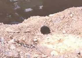
An example of a diversion dike/interceptor ditch placed across the crest
of a steep slope to intercept and prevent runoff from flowing down the face
of the slope is shown in Figure 3, below. In this case, the runoff diverted
and collected by the combined dike and ditch was conducted down the steep
slope in a chute that is out of sight in the photo.
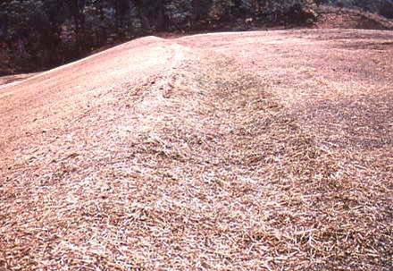
Figure 3. Example of a diversion dike placed along
the crest of a steep slope.
18. RESEARCH OPPORTUNITIES
No information available
19. REFERENCES
Gray, D. H. & Sotir, R. (1996). Biotechnical and Soil
Bioengineering Slope Stabilization. John Wiley and Sons, New York, N.
Y.
USDA. (1972). Minimizing Erosion in Urbanizing Areas.
USDA Soil Conservation Service, Madison, Wisconsin. Handbook developed in
cooperation with the Wisconsin Assoc. of Soil and Water Conservation Districts,
228 p