| FASCINES WITH
SUBSURFACE DRAIN |
 |
| FASCINES WITH
SUBSURFACE DRAIN |
|
1. CATEGORY
4.0 – Slope Stabilization
2. DESIGN STATUS
Level II
3. ALSO KNOWN AS
Fascines with Axial Subdrains.
4. DESCRIPTION
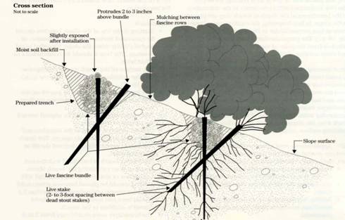
Rows of fascines are installed on contour on a slope in the conventional manner (see Technique: Live Fascines). In addition, a subsurface drain, oriented downslope and perpendicular to the fascines, is placed in a trench beneath the rows of fascines to intercept and collect seepage (Gray and Sotir, 1996; Kropp, 1989). The subsurface drain consists of a perforated pipe wrapped in a geo-composite drainage medium placed at the bottom of a trench. The trench is backfilled with clean, coarse aggregate or gravel.
5. PURPOSE
This system is used on very wet sites where there is evidence of substantial subsurface seepage that is causing piping and slope instability. The subsurface drain improves the effectiveness of the fascines, which might otherwise fail because of extremely wet conditions. The system can be considered as an alternative to fascines used as live pole drains (Gray and Sotir, 1986).
6. PLANNING
Useful for Erosion Processes:
Toe erosion with upper bank failure Scour of middle and upper banks by currents Local scour Erosion of local lenses or layers of noncohesive sediment Erosion by overbank runoff General bed degradation Headcutting Piping Erosion by navigation waves Erosion by wind waves Erosion by ice and debris gouging General bank instability or susceptibility to mass slope failure
Spatial Application:
Instream Toe Midbank Top of Bank
Hydrologic / Geomorphic Setting
Resistive Redirective Continuous Discontinuous Outer Bend Inner Bend Incision Lateral Migration Aggradation Conditions Where Practice Applies:
The system can be considered for use in filled gully areas or tributary swales where groundwater is likely to collect and concentrate.Complexity:
Moderate to High. Live Fascines are relatively simple and straightforward to fabricate and install. The subsurface drain adds another level of complexity because an axial trench must first be excavated, drain placed in the bottom, and then backfilled before the fascines can be installed across and over the trench.
Design Guidelines / Typical Drawings:
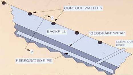
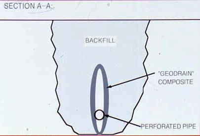
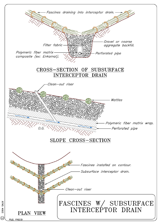
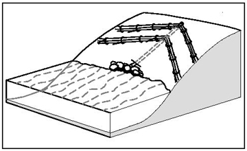
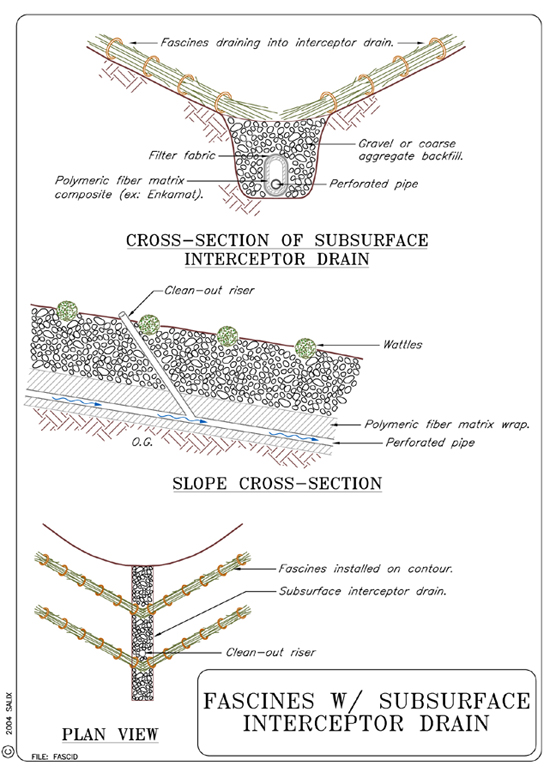
The seepage collection trench is excavated first, and a perforated pipe wrapped in a composite geodrain is placed in the bottom of the trench. The trench is then backfilled with gravel or coarse aggregate. The fascines are installed over and across the trench and subsurface drain as shown schematically in Figure 1. Fascines are prepared and installed in the conventional manner as described elsewhere (see Technique: Live Fascines). A cross section view of the subsurface drain or "geodrain" is shown in Figure 2. The geodrain is formed by first wrapping the perforated pipe in a three-dimensional open mat or matrix comprised of semi rigid polymeric fibers, e.g., Enkamat ™, followed by another wrap of filter fabric or filter cloth. The porous core of the geocomposite should face in towards the pipe, with the filter cloth backing facing outward. All drains should be constructed and installed with clean-out access tubes, as shown schematically in Figure 1. The perforated pipe in the subdrain should have sufficient capacity to handle and transmit intercepted groundwater flow or seepage. Guidelines for computing the appropriate size can be determined from published nomographs (see Technique: Trench Drain). Normally, a 10 cm (4 in) diameter polymeric pipe should suffice.
Figure 1. Profile view of a fascine system constructed over a subsurface interceptor drain
Figure 2. Cross-section view of a composite geodrain/ perforated pipe interceptor drain installed under a fascine systemAfter construction of the drain trench, the live fascines are installed over the trench in the normal manner (see Technique: Live Fascines). A schematic drawing of a typical live fascine installation is shown in Figure 3. Other than the presence of a clean out tube in the treatment including subsurface drainage, both techniques have the same external appearance.
Figure 3. Schematic drawing (profile view) of live fascine installation
7. ENVIRONMENTAL CONSIDERATIONS / BENEFITS
Wet conditions or excessive emergent seepage in a streambank can undo the
effectiveness of protective surface cover. The conjunctive use of fascines
and a subsurface interceptor drain helps to prevent this problem. Fascines
are made of live cuttings that root and grow, ensuring rapid establishment
of riparian vegetation with associated environmental benefits
8. HYDRAULIC LOADING
The considerations that apply to hydraulic loading of live fascines installed
on a streambank apply here as well (see Technique: Live
Fascines). The subdrain system is buried and not subjected to
hydraulic shear or tractive stresses during flood events.
9. COMBINATION OPPORTUNITIES
The conjunctive use of live fascines with an interceptor drain already constitutes
a combined practice of sorts. The system can also be used in combination
with Live Gully Fill Repair (see Technique: Live
Gully Repair) and with various types of river training techniques,
particularly protective toe structures (see Techniques: Longitudinal
Stone Toe, Longitudinal
Dikes with Toe Spurs).
10. ADVANTAGES
The same advantages that apply to the use of Live Fascines apply here as well.
In addition, the conjunctive use of a subsurface drain extends the
use of fascines in very wet areas, e.g., tributary swales, filled gullies,
and water bearing strata or lenses.
11. LIMITATIONS
Because of requirements for a trench in which to place a subsurface drain,
the maximum bank slope should be limited to no more than 1V:2H. The main limitation
is the feasibility and extra effort of excavating a trench down the face of
a streambank. The drain also has to be checked occasionally to insure that
it has not become clogged.
12. MATERIALS AND EQUIPMENT
In addition to the live cuttings required for the fascines, additional materials
are also required for manufacturing the drains, viz., perforated polymeric
pipe, filter cloth, and a turf reinforcement mat, e.g., Enkamat™,
for wrapping the pipe.
13. CONSTRUCTION / INSTALLATION
Fascines are prepared and installed in the conventional manner as described elsewhere (see Technique: Live Fascines). The seepage collection trench is excavated first, and a perforated pipe wrapped in a composite geodrain is placed in the bottom of the trench. The trench is then backfilled with gravel or coarse aggregate. The fascines are then installed on contour over and across the trench and subsurface drain. Row spacing guidelines for fascine installations are presented in Table 1.
TABLE 1: Recommended Spacings For Live Fascines On Slopes
Slope Steepness (V:H) |
Slope Distance Between |
|
On Contour |
On Angle |
|
1:1 to 1:1.5 |
0.9 – 1.2 (3 - 4) |
0.6 – 0.9 (2 – 3) |
1:1.5 to 1:2 |
1.2 – 1.5 (4 – 5) |
0.9 – 1.5 (3 – 5) |
1:2 to 1:2.5 |
1.5 – 1.8 (5 – 6) |
0.9 – 1.5 (3 – 5) |
1:2.5 to 1:3 |
1.8 – 2.4 (6 – 8) |
1.2 – 1.5 (4 – 5) |
1:3.5 to 1:4 |
2.4 – 2.7 (8 – 9) |
1.5 – 2.1 (5 – 7) |
1:4.5 to 1:5 |
2.7 – 3.0 (9 – 10) |
1.8 – 2.4 (6 – 8) |
14. COST
The installed cost of live fascines has been estimated at $26.24 - $328/m ($8 - 100/ft) (Washington, 2002). This wide discrepancy probably reflects the effect of site specific considerations (proximity and availability of live cuttings, ease of access, steepness and height of slope, etc). The requirement for installation of a subsurface interceptor drain will drive the cost towards the higher estimation. Given a bank 5 m (16.5 ft) high, with a 1V:2H slope and a swale or gully 20 m (65 ft) wide, installation of fascines with axial subdrain would be between $1,560 and $19,500 (including labor and materials, but not planning, design, administration or monitoring).
15. MAINTENANCE / MONITORING
The exit end of the subsurface drain should be checked periodically to insure
that water is flowing out of the drain. The subsurface drain pipe should
be flushed on a regular basis via the clean-out access tube to insure that
it flows freely and does not become clogged.
16. COMMON REASONS / CIRCUMSTANCES FOR FAILURE
The most common reasons for failure are improper design of the interceptor
drain placed at the bottom of the axial trench. The perforated pipe should
be correctly sized and wrapped with a suitable geodrain composite that excludes
fines but that lets water through. Failure to inspect and periodically flush
the drain via the clean-out access tube can also lead to clogging and poor
performance.
17. CASE STUDIES AND EXAMPLES
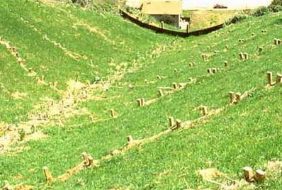
A fascine and subsurface interceptor drain system was used to stabilize
the track of a debris flow scar on a hillside in Pacifica, California (Kropp,
1989). The debris flow left a shallow swale that contained sufficient residual
soil in a vulnerable condition that was susceptible to both erosion and
future sliding. A fascine system was selected to stabilize the slope, but
significant amounts of both subsurface seepage and concentrated surface
runoff made additional drainage imperative. The tendency of both subsurface
seepage and runoff to concentrate naturally in the middle of the swale suggested
the use of a single, axial subsurface drain running up and down the slope
beneath the fascines. A photo of the combined system is shown in Figure
4. The outline of the central (axial) drainage trench is visible in the
photo. Grass and other native forbs were planted between fascine rows to
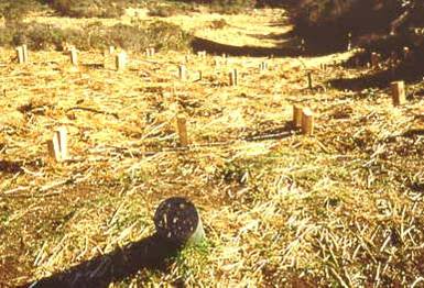
improve protection against surficial erosion. A view of the clean-out access
tube is shown in Figure 5. The site has remained stable with little or no
evidence of surface runoff or erosion.
|
|
18. RESEARCH OPPORTUNITIES
The combined use of Live Gully Repair and Live Fascines with Subsurface
Interceptor Drain and possible modifications deserve additional investigation.
19. REFERENCES
Gray, D. H. & Sotir, R. (1996). Biotechnical and Soil
Bioengineering Slope Stabilization. John Wiley and Sons, New York, N.
Y.
Kropp, A., Thomas, M., & Lucas, A. (1989). Biotechnical stabilization of a debris flow scar. Proceedings, XX International Erosion Control Association Conference, Vancouver, pp. 413-429.
Washington Dept of Fish & Wildlife (2003). Integrated Streambank
Protection Guidelines, published in co-operation with Washington
Dept. of Transportation and Washington Dept. of Ecology, June 2003. (Chapter
6 pdf) (Appendix
L pdf) (Appendix
H pdf) http://www.wa.gov/wdfw/hab/ahg/ispgdoc.htm (April
2003)