| TRENCH FILL REVETMENT |
 |
| TRENCH FILL REVETMENT |
|
1. CATEGORY
1.0 – River Training
2. DESIGN STATUS
Level II
3. ALSO KNOWN AS
Buried windrow revetment, riprap fill-trench, setback revetment.
4. DESCRIPTION
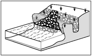
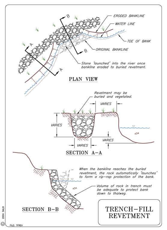
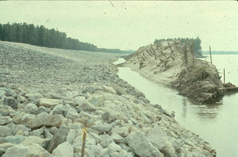
Trench fill revetments are constructed by excavating a trench along the top of the bank and placing stone riprap in the trench. As the bank erodes, the stone is undercut and "launches" down the bank line, resulting in a more gradual, protected slope. Earth removed for excavation of the trench may be used to cover the riprap, thus completely concealing it until it is launched (USACE, 1981).
5. PURPOSE
Trench fill revetments are installed to provide lateral stability to a channel by allowing natural erosive processes to form a gentle slope on the streambanks in reaches where some soil loss can be tolerated. The self launching stone provides a less intrusive technique for stabilization when compared to riprap installations on the entire bank, and eliminates the need for smoothing or flattening the slope.
6. PLANNING
Useful for Erosion Processes:
Toe erosion with upper bank failure Scour of middle and upper banks by currents Local scour Erosion of local lenses or layers of noncohesive sediment Erosion by overbank runoff General bed degradation Headcutting Piping Erosion by navigation waves Erosion by wind waves Erosion by ice and debris gouging General bank instability or susceptibility to mass slope failure
Spatial Application:
Instream Toe Midbank Top of Bank
Hydrologic / Geomorphic Setting
Resistive Redirective Continuous Discontinuous Outer Bend Inner Bend Incision Lateral Migration Aggradation Conditions Where Practice Applies:
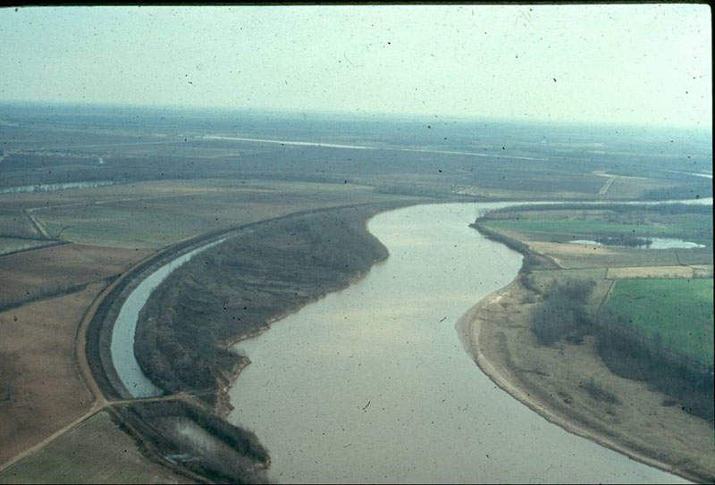
Trench fill revetments are placed along banks that are actively eroding, but where some additional bank loss can be tolerated. HEC-23 states that riprap fill-trench is effective in controlling lateral stream instability, but generally unsuitable for addressing local scour, contraction scour, or vertical stream instability. Controlling local scour at bridge abutments is listed as a possible secondary use. HEC-23 indicates that riprap fill trench is suitable for all types of river environments, and requires a moderate investment of resources for maintenance.
Trench Fill Revetments are often used where a smoothly aligned and stabilized channel is required, often for navigational purposes (Biedenharn, et. al., 1997). This is a good technique to use when construction within the stream channel is very difficult due to rapid erosion, high velocities, or other factors (Biedenharn, et. al., 1997).
Complexity:
Low.
Design Guidelines / Typical Drawings:
Trench-Fill Revetments should be constructed with well-graded, self-launching stone (USACE, 1981). Larger stone sizes will require thicker applications than smaller stones, to produce a revetment of the same relative thickness.
Shape of the stone toe is not critical. For trench-fill revetments, the height of the stone section is generally one-half to one times the length (Biedenharn, et. al., 1997).
7. ENVIRONMENTAL CONSIDERATIONS / BENEFITS
Excavation of the trench requires disturbance of a corridor along the
top bank, and therefore this measure is not recommended for sites where the
top bank supports valuable riparian vegetation. Terrestrial habitat values
of steep eroding banks where trench fill revetments are normally placed are
usually improved, especially if the revetment formed by the launched stone
and the top bank area disturbed by excavation is allowed to revegetate. Benthic
aquatic habitat at the bank toe may be improved by the addition of stable
substrate (Shields et al., 1995).
8. HYDRAULIC LOADING
Permissible shear and velocity for trench fill revetments is related to the
size of rock used in construction. Other factors, such as the angularity of
the stone, the thickness of the layers of stone, and the angle at which the
faces of the stone structure are constructed also come into play. Detailed
guidance for sizing stone for bed and bank stabilization structures is beyond
the scope of this guideline, and many approaches are available (See Special
Topic: Designing
Stone Structures). However, the Maynord (1995) equation gives
a D50 stone size for an angular stone riprap revetment of 0.875
m (2.9 ft) if the near-bank vertically-averaged velocity is 3.5 m/s (11.5
ft/s), and flow depth = 1 m (3.3 ft), and stone is placed on a bank slope
of 1V:1.5H. Use of riprap larger than this is unusual.
9. COMBINATION OPPORTUNITIES
Stone is sometimes piled along the top bank in a linear ridge called a windrow
revetment, instead of burying it in a trench.
10. ADVANTAGES
Eliminates underwater excavation.
Trench-Fill Revetments are simpler to design than a revetment placed on an actively eroding streambank (Biedenharn, et. al., 1997).
11. LIMITATIONS
Requires greater stone volume due to uncertainty in the launch process.
Requires noncohesive bank to properly function.
12. MATERIALS AND EQUIPMENT
Stone size and application rates for demonstration sites along the Missouri
River constructed in the late 1970s ranged from 10.4 to 17.9 t/m (3.5 to 6.0
T/ft) of bank protected. Stone sizes used for windrow revetments along larger
rivers have included 90 and 180 kg (200-lb and 400-lb) maximum size gradations
(Henderson and Shields, 1984).
13. CONSTRUCTION / INSTALLATION
Construction is usually conducted from the top of bank, and care should be exercised in operating heavy equipment at the top of steep banks (Keown, 1983). In addition, geotechnical analyses are recommended to examine the impact on bank slope stability of adding weight in the form of riprap fill. After erosion undermines the trench and stone begins to launch, stone may be added on an “as-needed” basis until the bank stabilizes. Alternatively, if the bank reaches a stable configuration without launching some of the stone, it may be excavated for use elsewhere. Site-specific conditions determine the amount of stone required to reach equilibrium.
14. COST
Construction costs for windrow revetment placed along the Missouri River ranged from $190 to $590 /m ($58 to $180/ft) of bank protected (1984 dollars) (Henderson and Shields, 1984). Costs per unit bank length of protected bank were slightly lower than those for other types of stone structures, such as reinforced revetment, composite revetment, hard points (short spurs), earth core dikes, and refusals (USACE, 1981).
15. MAINTENANCE / MONITORING
Trench fill revetments should be monitored following each significant storm event
through the first season and then on an annual basis to determine whether the
system is functioning properly. Rock may be added as needed once undermining
has occurred.
16. COMMON REASONS / CIRCUMSTANCES FOR FAILURE
Installation on streambanks composed of cohesive soils.
Increased bank instability due to the reduction of vegetation on the top bank as a result of excavation of the trench.
Inadequate size and quantity of rock that decreases chances of proper self launching.
Installation on a bank impacted by heavy local and contraction scour.
17. CASE STUDIES AND EXAMPLES
 |
 |
(from Workshop Notes, David Derrick, USACE) |
|
18. RESEARCH OPPORTUNITIES
None Identified
19. REFERENCES
Biedenharn, D. S., Elliott, C. M., & Watson, C. C. (1997). The
WES Stream Investigation and Streambank Stabilization Handbook. US
Army Engineer Waterways Experiment Station, Vicksburg, Mississippi. (pdf)
Henderson, J. E. and Shields, F. D., Jr. 1984. Environmental features for
bank protection projects. Technical Report E-84-11, U. S. Army Engineer
Waterways Experiment Station, Vicksburg, MS, 150 pp.
Keown, M. P. 1983. Streambank protection guidelines for landowners and local
governments. U. S. Army Engineer Waterways Experiment Station, Vicksburg,
Miss., 60 pp.
Lagasse, P. F., Byars, M. S., Zevenbergen, L. W. and Clopper, P. E. 1997. Bridge scour and stream instability countermeasures: Experience, selection and design guidance. Hydraulic Engineering Circular No. 23, FHWA HI 97-030, Washington, D. C., pp. 1.3-1.11. (pdf)
Shields, F. D., Jr., Cooper, C. M., and Testa, S. 1995. Towards greener
riprap: environmental considerations from micro- to macroscale. In C. R.
Thorne, S. R. Abt, F. B. J. Barends, S. T. Maynord, and K W. Pilarczyk.
(eds.). River, coastal and shoreline protection: erosion control using riprap
and armourstone. John Wiley & Sons, Ltd., Chichester, U. K., 557-574.
U. S. Army Corps of Engineers (USACE). 1981. Final Report to Congress, The
Streambank Erosion Control Evaluation and Demonstration Act of 1974, Section
32, Public Law 93-251. Main Report. Washington, D. C.
