| ROCK AND QUARRY
STONE REVETMENTS TO RESIST WAVE WASH |
|
Rock revetments must be placed on a prepared slope, keyed in at the toe, and placed high enough to avoid overtopping by wave runup. The bank should be graded to a 1V:1.5H side slope or flatter. The bottom of the revetment should be keyed into the base slightly below the anticipated scour line. Failure to observe this precaution compromises the effectiveness of a revetment. The method of placing riprap is important. Riprap may be hand-placed, end-dumped, or placed by derrick. For most applications, graded rock is placed by end dumping. When a bank must be protected against large wave forces, derrick-placed quarry stone is often used. The riprap must be placed on a filter blanket that is suitably sized to prevent the washout of fines through the armor layer. Either a graded aggregate or filter fabric can be used for this purpose. Care must be exercised to ensure that the blanket is not ruptured or displaced.
STABILITY REQUIREMENTSA revetment must be capable of armoring or protecting a slope and resisting displacement from tractive stresses exerted by high velocity water flows and/or wave action. The latter requirement is critical in the case of coastal slopes. It must allow for the exfiltration of water from the bank without permitting the movement of fines through the armor layer. Furthermore, a revetment should be imbedded sufficiently at its lower end to defend against scour and undermining. Finally, a revetment must be extended high enough up the slope to prevent overtopping from wave runup or conversely be equipped with an apron to mitigate the effects of such runup.
The following design guidelines (USACE, 1981) apply to quarry stone or rock riprap revetments used to protect coastal landforms (berms, bluffs, and beaches) against wave action.
Armor WeightRevetments protect coastal slopes and resist movement largely because of the weight and interlocking characteristics of individual armor units. The required weights are very sensitive to wave height, varying with the cube of the wave height. Other important parameters include the bank slope and the density and roughness properties of the armor units. The following equation can be used to estimate the required weight (W) of individual armor stones in relationship to the design wave height:
![]() (1)
(1)
| where: | W = weight of individual armor stones (lbs) |
| WR = unit wt. (saturated, surface dry) of rock (pcf) | |
| H = design wave height (ft) | |
| SR = specific gravity of armor stone | |
| cot Φ = slope of bank (H:V ratio) | |
| Kd = stability or roughness coefficient (see Table 1). |
TABLE 1: Roughness Coefficients for various types of armor stone
Armor Type |
Kd |
Quarry Stone smooth, rounded rough, angular |
2.1 3.5 |
Graded riprap |
2.2 |
Underlayer stones are used to provide a transition from the armor layer to the filter course. Underlayer stones should be sized at one tenth of the calculated armor stone weight.
Range of Allowable Stone WeightsThe recommended range for both the armor and underlayer is 0.75W to 1.25W with 75% of the stones weighing more than W. All stones should be shaped so that no side is longer than 3 times its least dimension.
Toe and Flank ProtectionThe toe should be buried (i.e., extended beneath the bottom of the slope) at least one design wave height. An additional layer of armor stone can be added to thicken the toe section. The revetment should also be tied into the existing bank on either side to prevent flanking.
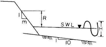
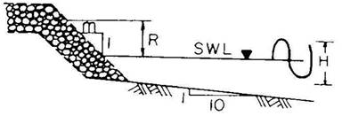
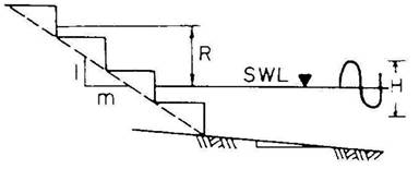
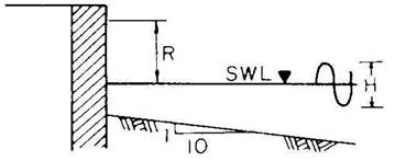
Runup CalculationsA revetment should be carried high enough up the bank or slope to prevent overtopping. Runup heights can be estimated as a function of design wave height and bank slope for different types of revetments from Table 2. If it is not possible to extend the revetment to the calculated runup height, then a splash apron must be used.
TABLE 2: Wave runup heights for revetments and seawalls
(from
USACE, 1981)
m |
R |
|
Smooth Face |
1.5 2.5 4.0 |
2.25 H 1.75 H 1.50 H |
Rough Face |
1.5 2.5 4.0 |
1.25 H 1.00 H 0.75 H |
Stepped Face |
1.5 |
2.0 H |
Vertical Face |
2.0 H |
U.S. Army Corps of Engineers (1981). Low cost shore protection: Final report on the shoreline erosion control demonstration program, Office of the Chief of Engineers, Washington, DC